We have a Facebook group!
If you’re into whitebox, disaggregated or commodity networking, come join the StubArea51.net Facebook group!
All network geeks are welcome 
|
||||||||


If you’re into whitebox, disaggregated or commodity networking, come join the StubArea51.net Facebook group!
All network geeks are welcome
|
||||||||
One of the challenges service providers have faced in the last decade is lowering the cost per port or per MB while maintaining the same level of availability and service level.
And then add to that the constant pressure from subscribers to increase capacity and meet the rising demand for realtime content.
This can be an especially daunting task when routers with the feature sets ISPs need cost an absolute fortune – especially as new port speeds are released.
Whitebox, also called disaggregated networking, has started changing the rules of the game. ISPs are working to figure out how to integrate and move to production on disaggregated models to lower the cost of investing in higher speeds and feeds.
Whitebox often faces the perception problem of being more difficult to implement than traditional vendors – which is exactly why I wanted to highlight some of the work we’ve been doing at iparchitechs.com integrating whitebox into production ISP networks using IP Infusion’s OcNOS.
Things are really starting to heat up in the disaggregagted network space after the announcement by Amazon a few days ago that it intends to build and sell whitebox switches.
As I write this, I’m headed to Networking Field Day 18 where IP Infusion will be presenting and I expect whitebox will again be a hot topic.
This will be the second time IPI has presented at Networking Field Day but the first time that I’ve had a chance to see them present firsthand.
It’s especially exciting for me as I work on implementing IPI on a regular basis and integrating OcNOS into client networks.
IP Infusion has been making network operating systems (NOS) for more than 20 years under the banner of its whitelabel NOS – ZebOS.
As disaggregated networking started to become popular, IPI created OcNOS which is an ONIE compatible NOS using elements and experience from 20 years of software development with ZebOS.
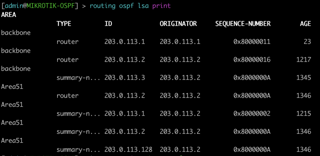
There is a great overview of OcNOS from Networking Field Day 15 here:
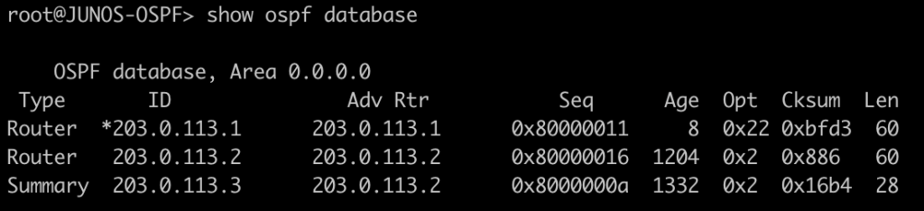
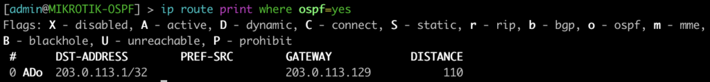
Here is an overview of the EVE-NG lab we built based on an actual implementation.
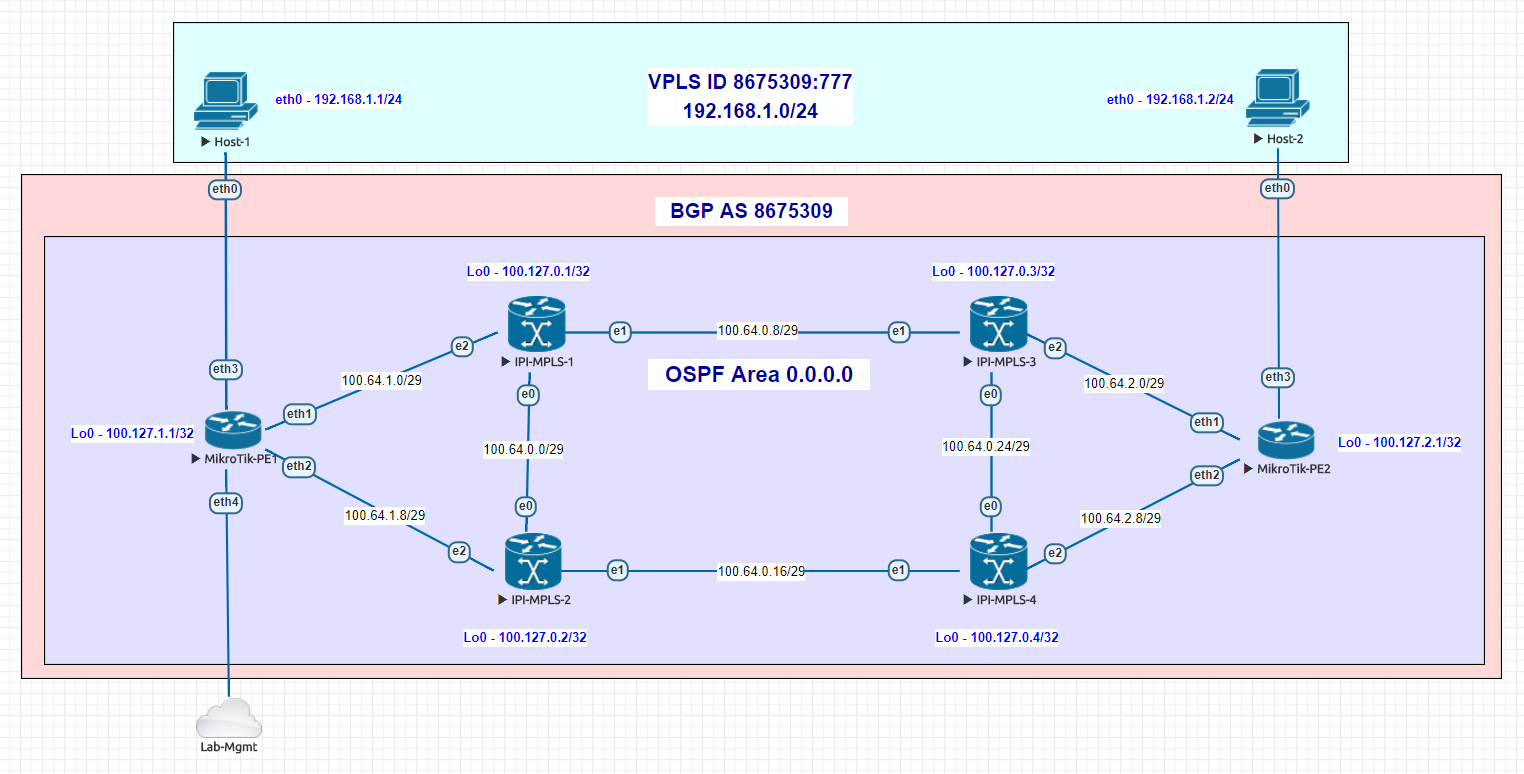
Use case – Building an MPLS core to deliver L2 overlay services
Although certainly not a new use case or implementation, MPLS and VPLS are very expensive to deploy using major vendors and are still a fundamental requirement for most ISPs.
This is where IPI really shines as they have feature sets like MPLS FRR, TE and the newer Segment Routing for OSPF and IS-IS that can be used in a platform that is significantly cheaper than incumbent network vendors.
The cost difference is so large that often ISPs are able to buy switches with a higher overall port speeds than they could from a major vendor. This in turn creates a significant competitive advantage as ISPs can take the same budget (or less) and roll out 100 gig instead of 10 gig – as an example
Unlike enterprise networks, cost is more consistently a significant driver when selecting network equipment for ISPs. This is especially true for startup ISPs that may be limited in the amount of capital that can be spent in a service area to keep ROI numbers relatively sane for investors.
In the lab (and production) network we have above, OcNOS is deployed as the MPLS core at each data center and MikroTik routers are being used as MPLS PE routers.
VPLS is being run from one DC to the other and delivered via the PE routers to the end hosts.
Because the port density on whitebox switches is so high compared to a traditional aggregation router, we could even use LACP channels if dark fiber was available to increase the transport bandwidth between the DCs without a significant monetary impact on the cost of the deployment.
The type of switches that you’d use in production depend greatly on the speeds and feeds required, but for startup ISPs, we’ve had lots of success with Dell 4048s and Edge-Core 5812.
It’s not hard at all!
If you know how to use the up and down arrow keys in the bootloader and TFTP/FTP to load an image onto a piece of network hardware, you’re halfway there!
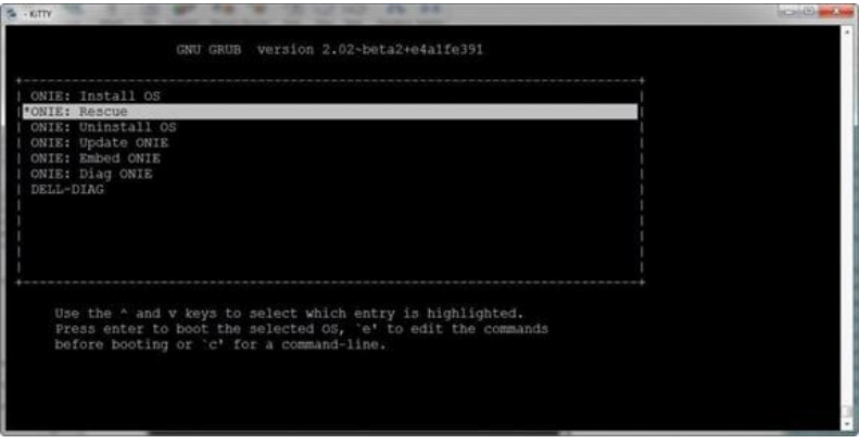
Here is a screenshot of the GRUB bootloader for an ONIE switch (this is a Dell) where you select which OS to boot the switch into
The configuration is relatively straightforward as well if you’re familiar with industry standard Command Line Interfaces (CLI).
While this lab was configured in a more traditional way using a terminal session to paste commands in, OcNOS can easily be orchestrated and automated using tools like Ansible (also presenting at Networking Field Day 18) or protocols like NETCONF as well as a REST API.
I’ve included the configs from the lab in order to give engineers a better idea of what OcNOS actually looks like for a production deployment.
IPI-MPLS-1
!
!Last configuration change at 12:24:27 EDT Tue Jul 17 2018 by ocnos
!
no service password-encryption
!
hostname IPI-MPLS-1
!
logging monitor 7
!
ip vrf management
!
mpls lsp-model uniform
mpls propagate-ttl
!
ip domain-lookup
spanning-tree mode provider-rstp
data-center-bridging enable
feature telnet
feature ssh
snmp-server enable snmp
snmp-server view all .1 included
ntp enable
username ocnos role network-admin password encrypted $1$HJDzvHS1$.4/PPuAmCUEwEhs
UWeYqo0
!
ip pim register-rp-reachability
!
router ldp
 router-id 100.127.0.1
!
interface lo
 mtu 65536
 ip address 127.0.0.1/8
 ip address 100.127.0.1/32 secondary
 ipv6 address ::1/128
!
interface eth0
 ip address 100.64.0.1/29
 label-switching
 enable-ldp ipv4
!
interface eth1
 ip address 100.64.0.9/29
 label-switching
 enable-ldp ipv4
!
interface eth2
 ip address 100.64.1.1/29
 label-switching
 enable-ldp ipv4
!
interface eth3
!
interface eth4
!
interface eth5
!
interface eth6
!
interface eth7
!
router ospf 1
 ospf router-id 100.127.0.1
 network 100.64.0.0/29 area 0.0.0.0
 network 100.64.0.8/29 area 0.0.0.0
 network 100.64.1.0/29 area 0.0.0.0
 network 100.127.0.1/32 area 0.0.0.0
 cspf disable-better-protection
!
bgp extended-asn-cap
!
router bgp 8675309
 bgp router-id 100.127.0.1
 neighbor 100.127.0.3 remote-as 8675309
 neighbor 100.127.0.3 update-source lo
 neighbor 100.127.2.1 remote-as 8675309
 neighbor 100.127.2.1 update-source lo
 neighbor 100.127.2.1 route-reflector-client
 neighbor 100.127.0.4 remote-as 8675309
 neighbor 100.127.0.4 update-source lo
 neighbor 100.127.0.4 route-reflector-client
 neighbor 100.127.0.2 remote-as 8675309
 neighbor 100.127.0.2 update-source lo
 neighbor 100.127.0.2 route-reflector-client
 neighbor 100.127.1.1 remote-as 8675309
 neighbor 100.127.1.1 update-source lo
 neighbor 100.127.1.1 route-reflector-client
!
line con 0
 login
line vty 0 39
 login
!
end
IPI-MPLS-2
!
!Last configuration change at 12:23:31 EDT Tue Jul 17 2018 by ocnos
!
no service password-encryption
!
hostname IPI-MPLS-2
!
logging monitor 7
!
ip vrf management
!
mpls lsp-model uniform
mpls propagate-ttl
!
ip domain-lookup
spanning-tree mode provider-rstp
data-center-bridging enable
feature telnet
feature ssh
snmp-server enable snmp
snmp-server view all .1 included
ntp enable
username ocnos role network-admin password encrypted $1$RWk6XAN.$6H0GXBR9ad8eJE2
7nRUfu1
!
ip pim register-rp-reachability
!
router ldp
 router-id 100.127.0.2
!
interface lo
 mtu 65536
 ip address 127.0.0.1/8
 ip address 100.127.0.2/32 secondary
 ipv6 address ::1/128
!
interface eth0
 ip address 100.64.0.2/29
 label-switching
 enable-ldp ipv4
!
interface eth1
 ip address 100.64.0.17/29
 label-switching
 enable-ldp ipv4
!
interface eth2
 ip address 100.64.1.9/29
 label-switching
 enable-ldp ipv4
!
interface eth3
!
interface eth4
!
interface eth5
!
interface eth6
!
interface eth7
!
router ospf 1
 network 100.64.0.0/29 area 0.0.0.0
 network 100.64.0.16/29 area 0.0.0.0
 network 100.64.1.8/29 area 0.0.0.0
 network 100.127.0.2/32 area 0.0.0.0
 cspf disable-better-protection
!
bgp extended-asn-cap
!
router bgp 8675309
 bgp router-id 100.127.0.2
 neighbor 100.127.0.3 remote-as 8675309
 neighbor 100.127.0.3 update-source lo
 neighbor 100.127.0.1 remote-as 8675309
 neighbor 100.127.0.1 update-source lo
!
line con 0
 login
line vty 0 39
 login
!
end
IPI-MPLS-3
!
!Last configuration change at 12:25:11 EDT Tue Jul 17 2018 by ocnos
!
no service password-encryption
!
hostname IPI-MPLS-3
!
logging monitor 7
!
ip vrf management
!
mpls lsp-model uniform
mpls propagate-ttl
!
ip domain-lookup
spanning-tree mode provider-rstp
data-center-bridging enable
feature telnet
feature ssh
snmp-server enable snmp
snmp-server view all .1 included
ntp enable
username ocnos role network-admin password encrypted $1$gc9xYbW/$JlCDmgAEzcCmz77
QwmJW/1
!
ip pim register-rp-reachability
!
router ldp
 router-id 100.127.0.3
!
interface lo
 mtu 65536
 ip address 127.0.0.1/8
 ip address 100.127.0.3/32 secondary
 ipv6 address ::1/128
!
interface eth0
 ip address 100.64.0.25/29
 label-switching
 enable-ldp ipv4
!
interface eth1
 ip address 100.64.0.10/29
 label-switching
 enable-ldp ipv4
!
interface eth2
 ip address 100.64.2.1/29
 label-switching
 enable-ldp ipv4
!
interface eth3
!
interface eth4
!
interface eth5
!
interface eth6
!
interface eth7
!
router ospf 1
 ospf router-id 100.127.0.3
 network 100.64.0.8/29 area 0.0.0.0
 network 100.64.0.24/29 area 0.0.0.0
 network 100.64.2.0/29 area 0.0.0.0
 network 100.127.0.3/32 area 0.0.0.0
 cspf disable-better-protection
!
bgp extended-asn-cap
!
router bgp 8675309
 bgp router-id 100.127.0.3
 neighbor 100.127.0.1 remote-as 8675309
 neighbor 100.127.0.1 update-source lo
 neighbor 100.127.2.1 remote-as 8675309
 neighbor 100.127.2.1 update-source lo
 neighbor 100.127.2.1 route-reflector-client
 neighbor 100.127.0.4 remote-as 8675309
 neighbor 100.127.0.4 update-source lo
 neighbor 100.127.0.4 route-reflector-client
 neighbor 100.127.0.2 remote-as 8675309
 neighbor 100.127.0.2 update-source lo
 neighbor 100.127.0.2 route-reflector-client
 neighbor 100.127.1.1 remote-as 8675309
 neighbor 100.127.1.1 update-source lo
 neighbor 100.127.1.1 route-reflector-client
!
line con 0
 login
line vty 0 39
 login
!
end
IPI-MPLS-4
!
!Last configuration change at 12:24:49 EDT Tue Jul 17 2018 by ocnos
!
no service password-encryption
!
hostname IPI-MPLS-4
!
logging monitor 7
!
ip vrf management
!
mpls lsp-model uniform
mpls propagate-ttl
!
ip domain-lookup
spanning-tree mode provider-rstp
data-center-bridging enable
feature telnet
feature ssh
snmp-server enable snmp
snmp-server view all .1 included
ntp enable
username ocnos role network-admin password encrypted $1$6OP7UdH/$RaIxCBOGxHIt1Ao
IUyPks/
!
ip pim register-rp-reachability
!
router ldp
 router-id 100.127.0.4
!
interface lo
 mtu 65536
 ip address 127.0.0.1/8
 ip address 100.127.0.4/32 secondary
 ipv6 address ::1/128
!
interface eth0
 ip address 100.64.0.26/29
 label-switching
 enable-ldp ipv4
!
interface eth1
 ip address 100.64.0.18/29
 label-switching
 enable-ldp ipv4
!
interface eth2
 ip address 100.64.2.9/29
 label-switching
 enable-ldp ipv4
!
interface eth3
!
interface eth4
!
interface eth5
!
interface eth6
!
interface eth7
!
router ospf 1
 ospf router-id 100.127.0.4
 network 100.64.0.16/29 area 0.0.0.0
 network 100.64.0.24/29 area 0.0.0.0
 network 100.64.2.8/29 area 0.0.0.0
 network 100.127.0.4/32 area 0.0.0.0
 cspf disable-better-protection
!
bgp extended-asn-cap
!
router bgp 8675309
 bgp router-id 100.127.0.4
 neighbor 100.127.0.3 remote-as 8675309
 neighbor 100.127.0.3 update-source lo
 neighbor 100.127.0.1 remote-as 8675309
 neighbor 100.127.0.1 update-source lo
!
line con 0
 login
line vty 0 39
 login
!
end
MikroTik PE-1
# jul/17/2018 17:33:30 by RouterOS 6.38.7
# software id =
#
/interface bridge
add name=Lo0
add name=bridge-vpls-777
/interface vpls
add disabled=no l2mtu=1500 mac-address=02:BF:0A:4A:55:D0 name=vpls777
    pw-type=tagged-ethernet remote-peer=100.127.2.1 vpls-id=8675309:777
/interface vlan
add interface=vpls777 name=vlan777 vlan-id=777
/interface wireless security-profiles
set [ find default=yes ] supplicant-identity=MikroTik
/routing bgp instance
set default as=8675309 router-id=100.127.1.1
/routing ospf instance
set [ find default=yes ] router-id=100.127.1.1
/interface bridge port
add bridge=bridge-vpls-777 interface=ether3
add bridge=bridge-vpls-777 interface=vlan777
/ip address
add address=100.64.1.2/29 interface=ether1 network=100.64.1.0
add address=100.127.1.1 interface=Lo0 network=100.127.1.1
add address=100.64.1.10/29 interface=ether2 network=100.64.1.8
/ip dhcp-client
add disabled=no interface=ether4
/mpls ldp
set enabled=yes lsr-id=100.127.1.1 transport-address=100.127.1.1
/mpls ldp interface
add interface=ether1 transport-address=100.127.1.1
add interface=ether2 transport-address=100.127.1.1
/routing bgp peer
add name=IPI-MPLS-1 remote-address=100.127.0.1 remote-as=8675309
    update-source=Lo0
add name=IPI-MPLS-3 remote-address=100.127.0.3 remote-as=8675309
    update-source=Lo0
/routing ospf network
add area=backbone network=100.64.1.0/29
add area=backbone network=100.64.1.8/29
add area=backbone network=100.127.1.1/32
/system identity
set name=MIkroTik-PE1
/tool romon
set enabled=yes
MikroTik PE-2
# jul/17/2018 17:34:23 by RouterOS 6.38.7
# software id =
#
/interface bridge
add name=Lo0
add name=bridge-vpls-777
/interface vpls
add disabled=no l2mtu=1500 mac-address=02:E2:86:F2:23:21 name=vpls777 pw-type=tagged-ethernet remote-peer=100.127.1.1 vpls-id=8675309:777
/interface vlan
add interface=vpls777 name=vlan777 vlan-id=777
/interface wireless security-profiles
set [ find default=yes ] supplicant-identity=MikroTik
/routing bgp instance
set default as=8675309 router-id=100.127.2.1
/routing ospf instance
set [ find default=yes ] router-id=100.127.2.1
/interface bridge port
add bridge=bridge-vpls-777 interface=ether3
add bridge=bridge-vpls-777 interface=vlan777
/ip address
add address=100.64.2.2/29 interface=ether1 network=100.64.2.0
add address=100.127.2.1 interface=Lo0 network=100.127.2.1
add address=100.64.2.10/29 interface=ether2 network=100.64.2.8
/ip dhcp-client
add disabled=no interface=ether1
/mpls ldp
set enabled=yes lsr-id=100.127.2.1 transport-address=100.127.2.1
/mpls ldp interface
add interface=ether1 transport-address=100.127.2.1
add interface=ether2 transport-address=100.127.2.1
/routing bgp peer
add name=IPI-MPLS-1 remote-address=100.127.0.1 remote-as=8675309 update-source=Lo0
add name=IPI-MPLS-3 remote-address=100.127.0.3 remote-as=8675309 update-source=Lo0
/routing ospf network
add area=backbone network=100.64.2.0/29
add area=backbone network=100.64.2.8/29
add area=backbone network=100.127.2.1/32
/system identity
set name=MIkroTik-PE2
/tool bandwidth-server
set authenticate=no
/tool romon
set enabled=yes

.
There are a number of ways to fund a startup Wireless Internet Service Provider (WISP), but the two we most commonly see as network engineering consultants at IP ArchiTechs are self funded by individuals/partners or by leveraging private equity (PE) money.
Private equity has become increasingly popular in the last few years if we are to use our consulting clients as a basis for comparison.
It’s not hard to see why, while you can (and many do) start a WISP on a shoestring budget, getting a significant chunk of initial funding to cover the costs of tower construction/leasing, network equipment, sales/marketing, etc is very attractive as it allows a WISP to build a network that might otherwise take several years of organic growth to achieve.
Many startup WISPs are often borne out of necessity – fast, reliable or economical Internet access – one or more of these is missing in the areas we see WISPs develop.
Typically the stakeholders come from a variety of backgrounds some of which are technical and some aren’t – all of them, however, share a vision of building out Internet access and solving problems that are unique to their corner of the world.
Out of that group, probably less than 5% come out of the ranks of professional network engineers.
And this isn’t to say that you need to be a network engineer to start a successful WISP, quite the contrary, the most successful WISPs are formed by people who understand what a well-run business looks like.
But when you’re in the business of building and selling access to a service provider IP network, at some point, you will benefit from having a network engineer as part of your team – whether that happens in the beginning or down the road is the core focus of this article.
.
Build it and then fix it later is probably the most common approach when it comes to the network design of a new WISP. Many startups (understandably) want to save money anywhere they can – consultants or tech labor costs can be steep when money is only going out and not coming in.
“Let’s just get it up and running so we can get some revenue and then we’ll fix things”
I’ve probably heard this phrase uttered a few hundred times when working with startup WISPs over the last decade.
This is the main reason bridged networks are so commonly found in startup WISPs. The network engineering is far simpler when everything is a single network and broadcast domain.
And it’s easy to see the allure of this approach – No subnetting, VLANs, routing protocols or advanced protocols like MPLS are required.
However, this is often the beginning of a painful journey for many WISPs that will result in an initial network redesign somewhere between 500 to 1000 subscribers as the broadcast domain will reach a point where performance starts to suffer and the mad dash to fix it begins.
Network redesigns are costly in the form of equipment, labor, downtime and lost opportunities. One of the key pieces of advice we give to prospective clients whether we work for them or not is to get someone that is a network professional involved with the network design from day one – whether it’s a consultant or an in house network engineer.
When we come in and perform a network redesign, there will be elements we use common to most ISP networks like:
Typically, the response we get from most clients is something like “wow, I wish I’d known about all of this before I started and just done it on day one – it would have been cheaper”
The cost of going through the redesign exercise can be substantial, even for a very small WISP, it can exceed $10k and for larger WISPs, it can easily be $100k or more.
It might seem like the list above is fairly complex for a very small network with only one tower and one Internet feed, but the reality is that if you build a design that’s ready to scale and template on day one, it will be far easier to grow quickly and not have to forklift those components in at a later date with large out of pocket costs.

.
When getting private equity firms to fund a new WISP, there are a number of budget items that go into the business plan but a plan to hire network engineers or consultants is rarely among them…why?
Many of the stakeholders involved in WISPs are often savvy tech people that are able to learn and digest new things quickly. I believe there is a perception that it’s less costly to start with a simplistic network design using the existing team and learn ‘on the fly’ rather than hire an experienced networker as a consultant or especially as an employee.
Before I get too much hate mail, there are plenty of success stories of WISPs that were built from the ground up that had to learn on the fly and were able to build a great network – so i’m not trying to paint a picture that it can’t ever be done.
The trial and error approach has a better chance of succeeding when you’re self-funded as you can gauge when you need help instead of getting hammered by investors when the network isn’t working well.
Private equity firms, however, are looking for a predictable return on their investment and skipping proper network design and planning with an experienced professional often puts a huge dent in the projected ROI for a number of reasons like:
And the list keeps going. These are just a few of the real-world examples we have seen that get categorized as “unforeseen costs.”
The key takeaway here for private equity firms and entrepreneurs that are seeking money via PE is to get professional network engineering incorporated into the budget at the beginning to minimize the list of “unforseen costs” in the first 180 to 365 days of network operation.
Whether you hire a consulting firm or a a full or part time network engineer to assist with this step, the key is to get someone who has experience with ISP operations and design – with WISPs especially.
The money saved from using a design validated by a professional will be likely be substantial and rapid growth is far easier when the network is built right from the beginning – both of these put the PE Firm and the WISP Owner/Operators in a great position to succeed and return value to investors in a shorter amount of time.
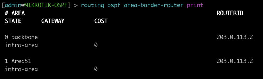
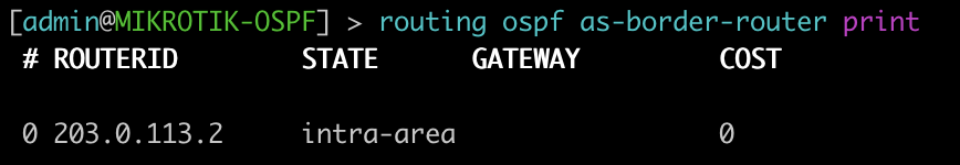
ISPs that use MikroTik are always looking for new ways to deliver services to customers and expand their offerings. Delivering Layer 2 at scale for customers is a design challenge that comes up frequently.
While it’s easy enough to build a VLAN nested inside of another VLAN (see below), this requires you to build all of the VLANs a customer wants to use into the PE router or handoff switch.
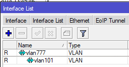
However, if you have a client that needs a layer 2 service delivered to two or more points and wants to be able to treat it just like an 802.1q trunk and add VLANs in an ad-hoc way, then using the S-Tag feature in RouterOS along with VPLS transport is a great option.
What’s the S-tag do???
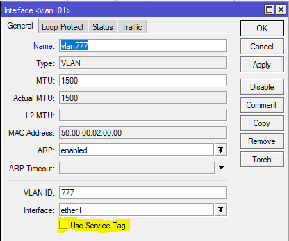
Clients will often ask me “what’s the S-Tag check box for?”
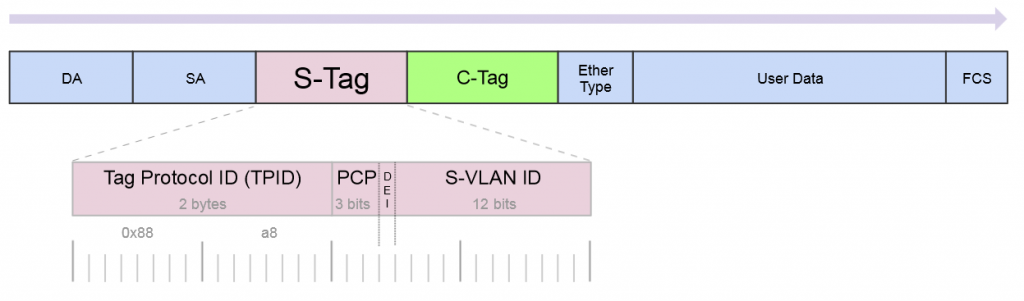
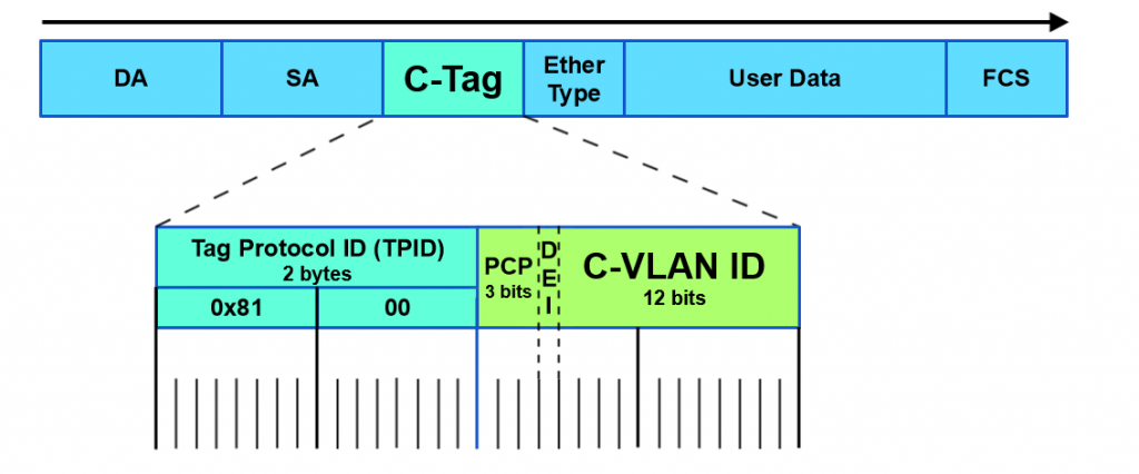
So a little background on this, there is a protocol for using outer and inner VLAN tags specified in IEEE 802.1ad that uses Service Tag (or S-Tag) to denote the outer VLAN tag used to transport Customer Tags (or C-Tags).
What makes the S-Tag/C-Tag a little bit different is that it actually changes the ethertype of the Frame.
| Protocol | Ethertype |
|---|---|
| 802.1q (Normal VLAN Tags) | 0x8100 |
| 802.1ad (S-tag) | 0x88a8 |
Here is an overview of the frame format of each and links to the Metro Ethernet Forum Wiki for more info.
S-Tag
https://wiki.mef.net/display/CESG/S-Tag
C-Tag
https://wiki.mef.net/display/CESG/C-Tag
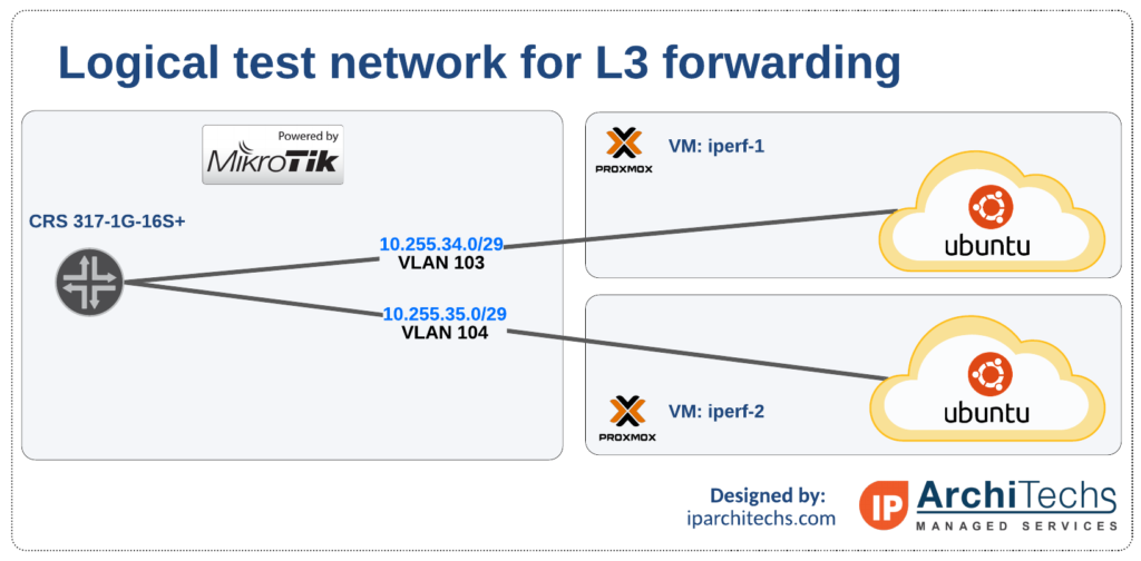
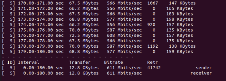
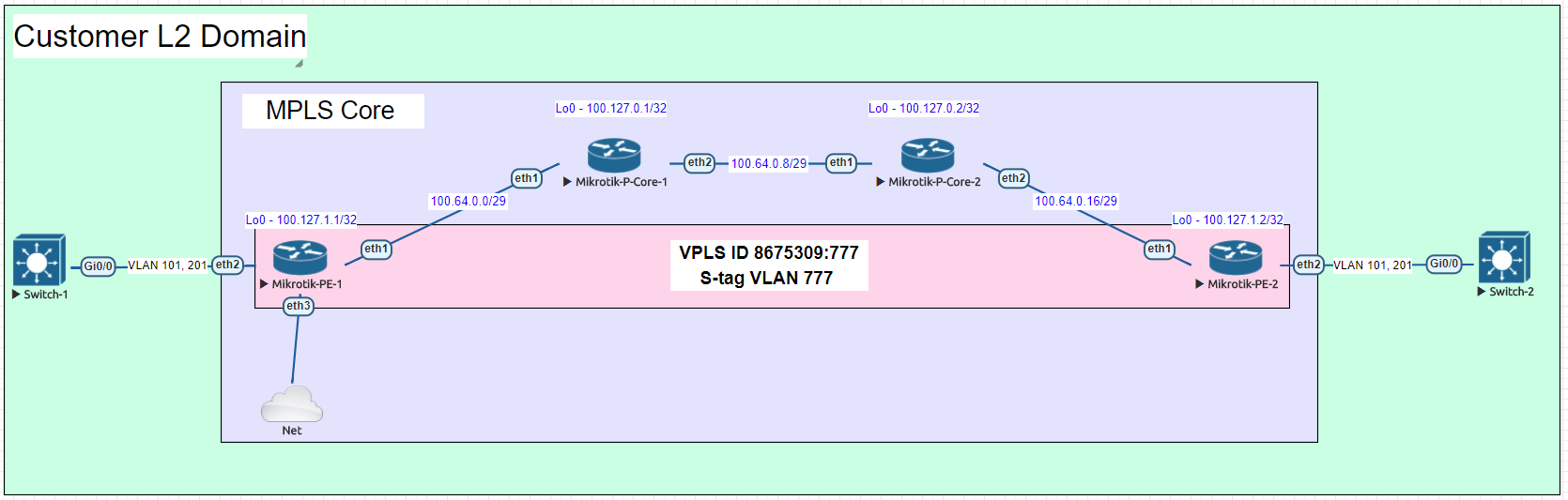
Here is a very common example of a deployment for a Layer 2 service to an end customer that rides on top of the ISP MPLS core.
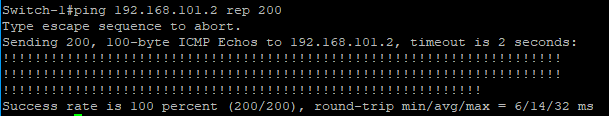
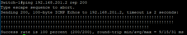
In this lab we are using Cisco switches trunked to each other using VLAN 101 and 201 over a VPLS pseudowire with an S-Tag of 777.
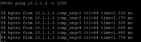
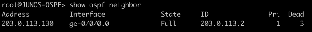
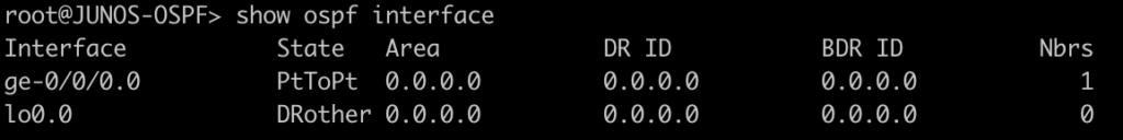
After configuring the P routers, PE routers and Cisco switches, let’s take a look at the Cisco switch and see if we can ping the SVI on the other switch on both trunked VLANs.
Here are the subnets used on the customer side:
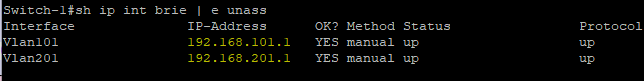
Now let’s ping the .2 address for each VLAN on Switch-2
VLAN 101
VLAN 201
A note on MTU sizing, in order to hand off a 1500 byte packet with VPLS, you normally need an MPLS and L2MTU of 1530 bytes. In order to pass a second VLAN tag you’ll want to make sure your network equipment can go up to 1534 for Layer 2 and MPLS MTUs to pass 1500 byte packet with S-Tag.
In the section below, here are all the configs for this deployment
Cisco Switch-1
version 15.2
service timestamps debug datetime msec
service timestamps log datetime msec
no service password-encryption
service compress-config
!
hostname Switch-1
!
boot-start-marker
boot-end-marker
!
!
!
no aaa new-model
!
!
!
!
!
!
!
!
ip cef
no ipv6 cef
!
!
!
spanning-tree mode pvst
spanning-tree extend system-id
!
vlan internal allocation policy ascending
!
!
!
!
!
!
!
!
!
!
!
!
!
!
interface GigabitEthernet0/0
 switchport trunk encapsulation dot1q
 switchport mode trunk
 media-type rj45
 negotiation auto
!
interface GigabitEthernet0/1
 media-type rj45
 negotiation auto
!
interface GigabitEthernet0/2
 media-type rj45
 negotiation auto
!
interface GigabitEthernet0/3
 media-type rj45
 negotiation auto
!
interface GigabitEthernet1/0
 media-type rj45
 negotiation auto
!
interface GigabitEthernet1/1
 media-type rj45
 negotiation auto
!
interface GigabitEthernet1/2
 media-type rj45
 negotiation auto
!
interface GigabitEthernet1/3
 media-type rj45
 negotiation auto
!
interface Vlan101
 description customer-vlan
 ip address 192.168.101.1 255.255.255.0
!
interface Vlan201
 description customer vlan 2
 ip address 192.168.201.1 255.255.255.0
!
ip forward-protocol nd
!
no ip http server
no ip http secure-server
!
!
!
!
!
!
control-plane
!
banner exec ^C
**************************************************************************
* IOSv is strictly limited to use for evaluation, demonstration and IOS  *
* education. IOSv is provided as-is and is not supported by Cisco's      *
* Technical Advisory Center. Any use or disclosure, in whole or in part, *
* of the IOSv Software or Documentation to any third party for any       *
* purposes is expressly prohibited except as otherwise authorized by     *
* Cisco in writing.                                                      *
**************************************************************************^C
banner incoming ^C
**************************************************************************
* IOSv is strictly limited to use for evaluation, demonstration and IOS  *
* education. IOSv is provided as-is and is not supported by Cisco's      *
* Technical Advisory Center. Any use or disclosure, in whole or in part, *
* of the IOSv Software or Documentation to any third party for any       *
* purposes is expressly prohibited except as otherwise authorized by     *
* Cisco in writing.                                                      *
**************************************************************************^C
banner login ^C
**************************************************************************
* IOSv is strictly limited to use for evaluation, demonstration and IOS  *
* education. IOSv is provided as-is and is not supported by Cisco's      *
* Technical Advisory Center. Any use or disclosure, in whole or in part, *
* of the IOSv Software or Documentation to any third party for any       *
* purposes is expressly prohibited except as otherwise authorized by     *
* Cisco in writing.                                                      *
**************************************************************************^C
!
line con 0
line aux 0
line vty 0 4
!
!
end
Cisco Switch-2
version 15.2
service timestamps debug datetime msec
service timestamps log datetime msec
no service password-encryption
service compress-config
!
hostname Switch-2
!
boot-start-marker
boot-end-marker
!
!
!
no aaa new-model
!
!
!
!
!
!
!
!
ip cef
no ipv6 cef
!
!
!
spanning-tree mode pvst
spanning-tree extend system-id
!
vlan internal allocation policy ascending
!
!
!
!
!
!
!
!
!
!
!
!
!
!
interface GigabitEthernet0/0
 switchport trunk encapsulation dot1q
 switchport mode trunk
 media-type rj45
 negotiation auto
!
interface GigabitEthernet0/1
 media-type rj45
 negotiation auto
!
interface GigabitEthernet0/2
 media-type rj45
 negotiation auto
!
interface GigabitEthernet0/3
 media-type rj45
 negotiation auto
!
interface GigabitEthernet1/0
 media-type rj45
 negotiation auto
!
interface GigabitEthernet1/1
 media-type rj45
 negotiation auto
!
interface GigabitEthernet1/2
 media-type rj45
 negotiation auto
!
interface GigabitEthernet1/3
 media-type rj45
 negotiation auto
!
interface Vlan101
 description customer-vlan
 ip address 192.168.101.2 255.255.255.0
!
interface Vlan201
 description customer vlan 2
 ip address 192.168.201.2 255.255.255.0
!
ip forward-protocol nd
!
no ip http server
no ip http secure-server
!
!
!
!
!
!
control-plane
!
banner exec ^C
**************************************************************************
* IOSv is strictly limited to use for evaluation, demonstration and IOS  *
* education. IOSv is provided as-is and is not supported by Cisco's      *
* Technical Advisory Center. Any use or disclosure, in whole or in part, *
* of the IOSv Software or Documentation to any third party for any       *
* purposes is expressly prohibited except as otherwise authorized by     *
* Cisco in writing.                                                      *
**************************************************************************^C
banner incoming ^C
**************************************************************************
* IOSv is strictly limited to use for evaluation, demonstration and IOS  *
* education. IOSv is provided as-is and is not supported by Cisco's      *
* Technical Advisory Center. Any use or disclosure, in whole or in part, *
* of the IOSv Software or Documentation to any third party for any       *
* purposes is expressly prohibited except as otherwise authorized by     *
* Cisco in writing.                                                      *
**************************************************************************^C
banner login ^C
**************************************************************************
* IOSv is strictly limited to use for evaluation, demonstration and IOS  *
* education. IOSv is provided as-is and is not supported by Cisco's      *
* Technical Advisory Center. Any use or disclosure, in whole or in part, *
* of the IOSv Software or Documentation to any third party for any       *
* purposes is expressly prohibited except as otherwise authorized by     *
* Cisco in writing.                                                      *
**************************************************************************^C
!
line con 0
line aux 0
line vty 0 4
!
!
end
MikroTik PE-1
/interface bridge
add name=Lo0
add name=vpls-bridge-vlan-777
/interface vpls
add disabled=no l2mtu=1500 mac-address=02:D5:C2:72:3A:1A name=vpls777
    pw-type=tagged-ethernet remote-peer=100.127.1.2 vpls-id=8675309:777
/ip neighbor discovery
set ether2 discover=no
/interface vlan
add interface=vpls777 name=vlan777 use-service-tag=yes vlan-id=777
/interface wireless security-profiles
set [ find default=yes ] supplicant-identity=MikroTik
/routing ospf instance
add name=ospf1 router-id=100.127.1.1
/interface bridge port
add bridge=Lo0 interface=ether2
add bridge=Lo0 interface=vlan777
/ip address
add address=100.64.0.1/29 interface=ether1 network=100.64.0.0
add address=100.127.1.1 interface=Lo0 network=100.127.1.1
/ip dhcp-client
add disabled=no interface=ether1
/mpls interface
set [ find default=yes ] mpls-mtu=1534
/mpls ldp
set enabled=yes lsr-id=100.127.1.1 transport-address=100.127.1.1
/mpls ldp interface
add interface=ether1 transport-address=100.127.1.1
/routing ospf network
add area=backbone network=100.64.0.0/29
add area=backbone network=100.127.1.1/32
/system identity
set name=MikroTik-PE-1
/tool romon
set enabled=yes
MikroTik PE-2
/interface bridge
add name=Lo0
add name=vpls-bridge-vlan-777
/interface vpls
add disabled=no l2mtu=1500 mac-address=02:C1:71:EB:0E:E7 name=vpls777
    pw-type=tagged-ethernet remote-peer=100.127.1.1 vpls-id=8675309:777
/ip neighbor discovery
set ether2 discover=no
/interface vlan
add interface=vpls777 name=vlan777-s-tag use-service-tag=yes vlan-id=777
/interface wireless security-profiles
set [ find default=yes ] supplicant-identity=MikroTik
/routing ospf instance
add name=ospf1 router-id=100.127.1.2
/interface bridge port
add bridge=Lo0 interface=vlan777-s-tag
add bridge=Lo0 interface=ether2
/ip address
add address=100.64.0.18/29 interface=ether1 network=100.64.0.16
add address=100.127.1.2 interface=Lo0 network=100.127.1.2
/ip dhcp-client
add dhcp-options=hostname,clientid disabled=no interface=ether1
/mpls interface
set [ find default=yes ] mpls-mtu=1534
/mpls ldp
set enabled=yes lsr-id=100.127.1.2 transport-address=100.127.1.2
/mpls ldp interface
add interface=ether1 transport-address=100.127.1.2
/routing ospf network
add area=backbone network=100.64.0.16/29
add area=backbone network=100.127.1.2/32
/system identity
set name=MikroTik-PE-2
/tool romon
set enabled=yes
MikroTik P-CORE-1
/interface bridge
add name=Lo0
/interface vlan
add interface=ether1 name=vlan101 vlan-id=777
/interface wireless security-profiles
set [ find default=yes ] supplicant-identity=MikroTik
/routing ospf instance
set [ find default=yes ] router-id=100.127.0.1
/ip address
add address=100.64.0.2/29 interface=ether1 network=100.64.0.0
add address=100.127.0.1 interface=Lo0 network=100.127.0.1
add address=100.64.0.9/29 interface=ether2 network=100.64.0.8
/ip dhcp-client
add dhcp-options=hostname,clientid disabled=no interface=ether1
/mpls interface
set [ find default=yes ] mpls-mtu=1534
/mpls ldp
set enabled=yes lsr-id=100.127.0.1 transport-address=100.127.0.1
/mpls ldp interface
add interface=ether1 transport-address=100.127.0.1
add interface=ether2 transport-address=100.127.0.1
/routing ospf network
add area=backbone network=100.64.0.0/29
add area=backbone network=100.127.0.1/32
add area=backbone network=100.64.0.8/29
/system identity
set name=MikroTik-P-Core-1
/tool romon
set enabled=yes
MikroTik P-CORE-2
/interface bridge
add name=Lo0
/interface wireless security-profiles
set [ find default=yes ] supplicant-identity=MikroTik
/routing ospf instance
set [ find default=yes ] router-id=100.127.0.2
/ip address
add address=100.64.0.10/29 interface=ether1 network=100.64.0.8
add address=100.127.0.2 interface=Lo0 network=100.127.0.2
add address=100.64.0.17/29 interface=ether2 network=100.64.0.16
/ip dhcp-client
add dhcp-options=hostname,clientid disabled=no interface=ether1
/mpls interface
set [ find default=yes ] mpls-mtu=1534
/mpls ldp
set enabled=yes lsr-id=100.127.0.2 transport-address=100.127.0.2
/mpls ldp interface
add interface=ether1 transport-address=100.127.0.2
add interface=ether2 transport-address=100.127.0.2
/routing ospf network
add area=backbone network=100.64.0.8/29
add area=backbone network=100.127.0.2/32
add area=backbone network=100.64.0.16/29
/system identity
set name=MikroTik-P-Core-2
/tool romon
IPv6 is one of those technologies that can feel pretty overwhelming, but it doesn’t have to be. Many of the same ideas and concepts learned in IPv4 networking still apply.
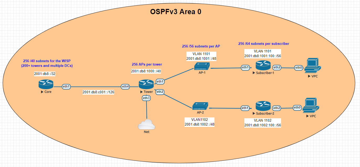
This guide is meant to give you an overview of an example IPv6 addressing plan for an entire WISP as well as the config needed in MikroTik to deploy IPv6 from a core router all the way to a subscriber device.
One of the things i’ve learned about IPv6 is that addressing plans seem to spark epic debates about the waste of addresses and what size prefix an end subscriber should get.
Although this lab could have easily been done with a /56 at the tower and /53 at each AP, I decided to use RIPEs recommendations from their guide on IPv6 best operational practices.
This is mainly to keep the focus of the article on actually getting IPv6 deployed and not focusing on the addressing.
For simplicity, the IPv4 config is not shown, but the recommended design for an operational WISP is to implement IPv4 and IPv6 side by side in a Dual Stack configuration.
The lab is designed to illustrate most of the operational aspects of IPv6 in a WISP using MikroTik CHR routers in EVE-NG. This includes:

In the lab, the core router is shown directly connected to the tower for simplicity, in your WISP, there may be multiple towers between the core and the end of the network.
The concept, however is the same – use /126 addressing to connect towers for OSPFv3.
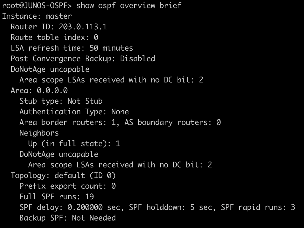
Note that OSPFv3 still requires a router-id in dotted decimal format, even though the address you put int doesn’t have to actually exist – for consistency however, use the IPv4 loopback of the router for the router id.
The internet connectivity isn’t shown in this lab, but your ISP will give you a /126 address to connect to your border router and either peer with BGP or the provider can route the /32 prefix to you.
Config
/interface wireless security-profiles
set [ find default=yes ] supplicant-identity=MikroTik
/routing ospf-v3 instance
set [ find default=yes ] distribute-default=always-as-type-1 router-id=\
    100.127.1.1
/ip dhcp-client
add disabled=no interface=ether1
/ipv6 address
add address=2001:db8:c001::1/126 advertise=no interface=ether1
/routing ospf-v3 interface
add area=backbone interface=ether1
/system identity
set name=Core
/tool romon
set enabled=yes
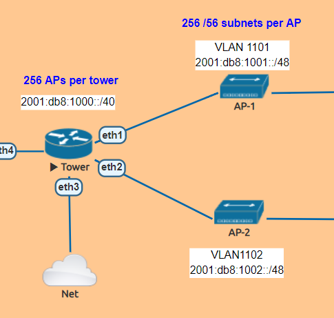
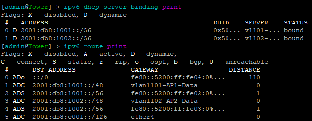
The tower router is handling most of the work as it is responsible for DHCPv6 and Prefix Delegation as well as advertising the /48 AP subnets into OSPF
In this lab , the APs are split into separate VLANs (with dual stack, IPv4 would exist on the same VLAN).
The router is configured to hand out /56 prefixes to the end subscriber using a pool of /48 per AP.
Because Prefix Delegation is being utilized, a dynamic static route is created for each /56 the DHCPv6 server hands out which eliminates the need to use a routing protocol.
Prefix Delegation in action
This example shows the prefixes allocated by the router and the dynamic static routes created
Config
/interface bridge
add name=Lo0
/interface vlan
add interface=ether1 name=vlan1101-AP1-Data vlan-id=1101
add interface=ether2 name=vlan1102-AP2-Data vlan-id=1102
/interface wireless security-profiles
set [ find default=yes ] supplicant-identity=MikroTik
/ipv6 dhcp-server
add address-pool=vl101-v6-pd-pool interface=vlan1101-AP1-Data name=\
    vl101-v6-pd
add address-pool=vl102-v6-pd-pool interface=vlan1102-AP2-Data name=\
    vl102-v6-pd
/ipv6 pool
add comment="VLAN1101 IPv6 prefix delegation pool" name=vl101-v6-pd-pool \
    prefix=2001:db8:1001::/48 prefix-length=56
add comment="VLAN1102 IPv6 prefix delegation pool" name=vl102-v6-pd-pool \
    prefix=2001:db8:1002::/48 prefix-length=56
/routing ospf-v3 instance
set [ find default=yes ] router-id=100.127.1.2
/ip dhcp-client
add disabled=no interface=ether1
/ipv6 address
add address=2001:db8:1001::1/48 advertise=no interface=vlan1101-AP1-Data
add address=2001:db8:1002::1/48 advertise=no interface=vlan1102-AP2-Data
add address=2001:db8:c001::2/126 advertise=no interface=ether4
/ipv6 nd
add interface=vlan1101-AP1-Data managed-address-configuration=yes \
    other-configuration=yes
add interface=vlan1102-AP2-Data managed-address-configuration=yes \
    other-configuration=yes
/ipv6 nd prefix
add autonomous=no interface=vlan1101-AP1-Data
add autonomous=no interface=vlan1102-AP2-Data
/routing ospf-v3 interface
add area=backbone interface=ether4
add area=backbone interface=vlan1101-AP1-Data
add area=backbone interface=vlan1102-AP2-Data
add area=backbone passive=yes
/system identity
set name=Tower
/tool romon
set enabled=yes

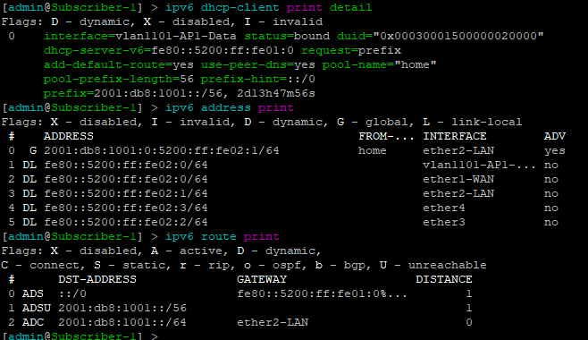
For simplicity, MikroTik is used as the Subscriber or CPE router to provide an example of how the /56 prefix is received from the tower router and handed off to devices inside the subscriber’s home.
In this lab, the “WAN” interface or ether1 has a DHCPv6 client configured to receive the prefix from the tower router.
Ether2 or the “LAN” side, which would include a bridge of the the wireless/wired interfaces in a real router is configured with a dynamic /64 from the /56 pool and is set for SLAAC to give devices on this segment an IPv6 address.
DHCPv6 client and subscriber addresses/routes
Config – Subscriber 1
/interface ethernet
set [ find default-name=ether1 ] name=ether1-WAN
set [ find default-name=ether2 ] name=ether2-LAN
/interface vlan
add interface=ether1-WAN name=vlan1101-AP1-Data vlan-id=1101
/interface wireless security-profiles
set [ find default=yes ] supplicant-identity=MikroTik
/ip dhcp-client
add disabled=no interface=ether1-WAN
/ipv6 address
add eui-64=yes from-pool=home interface=ether2-LAN
/ipv6 dhcp-client
add add-default-route=yes interface=vlan1101-AP1-Data pool-name=home \
    pool-prefix-length=56 request=prefix
/ipv6 nd
add hop-limit=64 interface=ether2-LAN
/system identity
set name=Subscriber-1
/tool romon
set enabled=yes
Config – Subscriber 2
/interface ethernet
set [ find default-name=ether1 ] name=ether1-WAN
set [ find default-name=ether2 ] name=ether2-LAN
/interface vlan
add interface=ether1-WAN name=vlan1102-AP2-Data vlan-id=1102
/interface wireless security-profiles
set [ find default=yes ] supplicant-identity=MikroTik
/ip dhcp-client
add disabled=no interface=ether1-WAN
/ipv6 address
add eui-64=yes from-pool=home interface=ether2-LAN
/ipv6 dhcp-client
add add-default-route=yes interface=vlan1102-AP2-Data pool-name=home \
    pool-prefix-length=56 request=prefix
/ipv6 nd
add hop-limit=64 interface=ether2-LAN
/system identity
set name=Subscriber-2
/tool romon
set enabled=yes
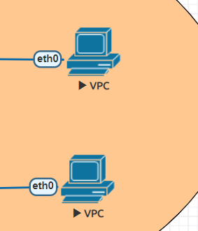
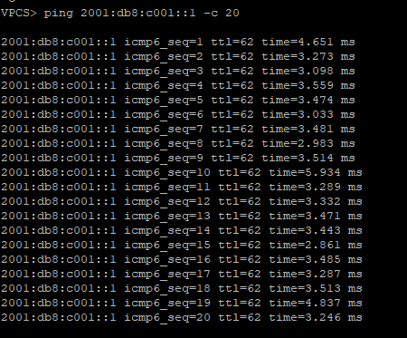
EVE-NG has a small Linux image that can be used as a host called VPC or virtual PC. This allows us to put a device on ether2 and test end to end reachability back to the core router.
SLAAC addressing example

Ping test back to the core router
Success!!!!!!!!
The team at IP ArchiTechs has decades of experience in networking and specializes in WISP design, troubleshooting and operation. Click on the graphic below to contact IP ArchiTechs and get help with your networking problems.
One of the most difficult configuration challenges for MikroTik equipment seems to be switching and VLANs in the CRS series. Admittedly, the revamp of VLAN configuration for MikroTik CRS switches in early 2018 made things a lot easier. But, sometimes there is still confusion on how to configure VLANs and IP addresses in VLANs with MikroTik RouterOS operating on a switch.
This will only cover VLAN configuration for CRS 3xx series switches in RouterOS as SwitchOS is not nearly as common in operational deployments.
CRS 1xx/2xx series use an older style of configuration and seem to be on the way out so I’m not 100% sure whether or not i’ll write a similar guide on that series.
If you’ve been in networking for a while, you probably started with learning the Cisco CLI. Therefore, it is helpful to compare the commands if you want to implement a network with a MikroTik and Cisco switches.
This is the fourth post in a series that creates a Rosetta stone between IOS and RouterOS. Here are some of the others:
Click here for the first article in this series – “Cisco to MikroTik BGP command translation”
Click here for the second article in this series – “Cisco to MikroTik OSPF command translation”
Click here for the third article in the series – “Cisco to MikroTik MPLS command translation”
While many commands have almost the exact same information, others are as close as possible. Since there isn’t always an exact match, sometimes you may have to run two or three commands to get the information needed.
In the last article, we began using EVE-NG instead of GNS3 to emulate both Cisco IOS and RouterOS so we could compare the different commands and ensure the translation was as close as possible. However in switching, we still have to use real hardware at least in the realm of MikroTik – Cisco has IOSvL2 images that can be used in EVE-NG for switching.
Bridging is a very confusing topic within the realm of MikroTik equipment. It is often associated with CPU forwarding and is generally seen as something to be avoided if at all possible.
There are a few reasons for this…
1. Within routers, bridging generally does rely on the CPU for forwarding and the throughput is limited to the size of the CPU.
2. In the previous generation of CRS configuration, bridging was not the best way to configure the switch – using the port master/slave option would trigger hardware forwarding.
After MikroTik revamped the switch config for VLANs in 2018 to utilize the bridge, it more closely resembles the style of configuration for Metro Ethernet Layer 2 as well as vendors like Juniper that use the ‘bridge-domain’ style of config.
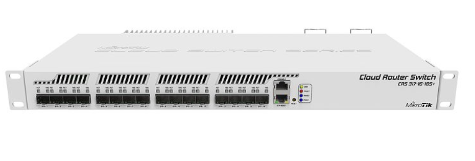
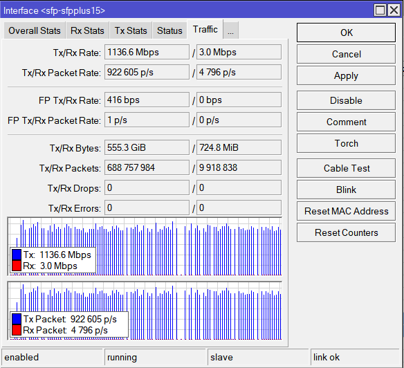
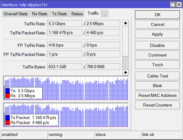
Using the bridge for hardware offload of L2 traffic
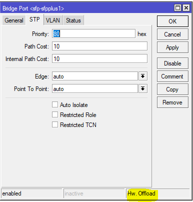
Note the Hw. Offload verification under this bridge port in the CRS317
It is important to realize that bridging in the CRS, when used for VLAN configuration is actually using the switch ASIC to forward traffic and not the CPU.
In this instance, the bridge is merely used as a familiar configuration tool to tie ports and VLANs together but does in fact allow for the forwarding of traffic in hardware at wirespeed.
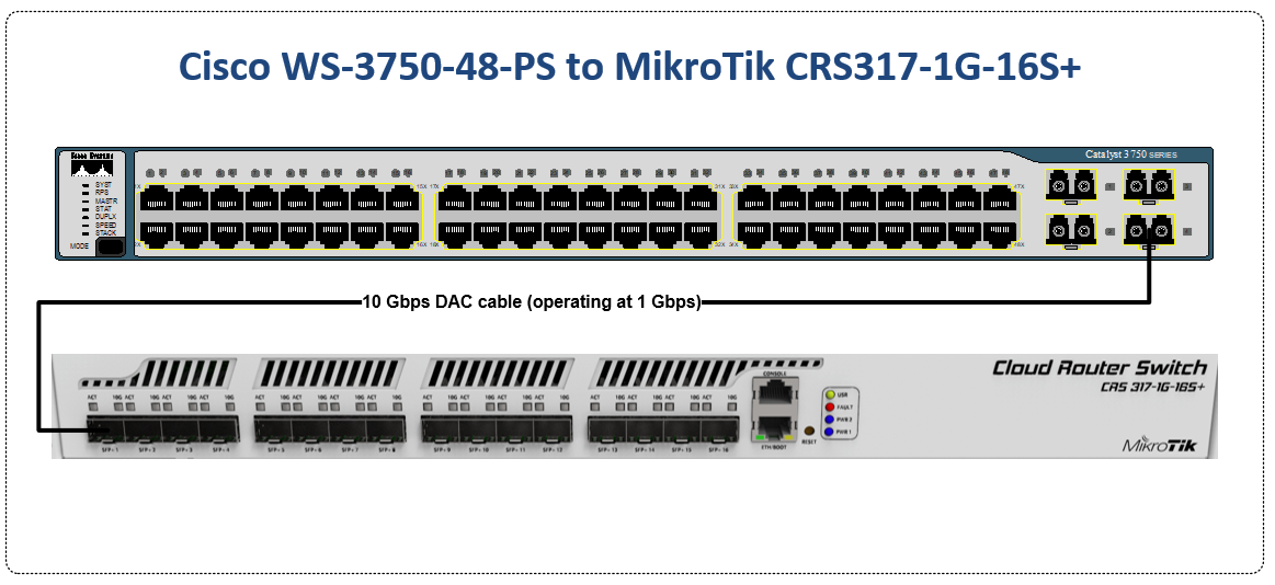
Cisco to MikroTik – command translation
| Cisco command | MikroTik Command |
|---|---|
| interface FastEthernet5/0/47 switchport access vlan 100 switchport mode access end | /interface bridge port add bridge=bridge1 interface=sfp-sfpplus1 pvid=100 |
| interface GigabitEthernet5/0/4 switchport trunk encapsulation dot1q switchport trunk allowed vlan 200 switchport mode trunk end | /interface bridge vlan add bridge=bridge1 tagged=sfp-sfpplus1 vlan-ids=200 |
| interface Vlan200 ip address 172.16.1.254 255.255.255.0 end | /interface vlan add interface=bridge1 name=vlan200 vlan-id=200 /interface bridge vlan add bridge=bridge1 tagged=sfp-sfpplus1,bridge1 vlan-ids=200 /ip address add address=172.16.1.254/24 interface=vlan200 network=172.16.1.0 |
| spanning-tree mode mst | /interface bridge add fast-forward=no name=bridge1 priority=0 protocol-mode=mstp region-name=main vlan-filtering=yes |
| interface FastEthernet5/0/47 switchport access vlan 200 switchport mode access spanning-tree portfast end | interface bridge port set edge=yes-discover |
| interface GigabitEthernet5/0/4 switchport trunk encapsulation dot1q switchport trunk allowed vlan 200 switchport mode trunk channel-group 1 mode active end interface Port-channel1 switchport trunk encapsulation dot1q switchport trunk allowed vlan 200 switchport mode trunk end | interface bonding add mode=802.3ad name=Po1 slaves=sfp-sfpplus1,sfp-sfpplus3 \ transmit-hash-policy=layer-2-and-3 /interface bridge vlan add bridge=bridge1 tagged=Po1,bridge1 vlan-ids=200 |
| show mac address-table | interface bridge host print |
| show mac address-table vlan 200 | interface bridge host print where vid=200 |
| show mac address-table interface Gi5/0/4 | interface bridge host print where interface=sfp-sfpplus1 |
| show interfaces trunk show vlan | interface bridge vlan print |
| show spanning-tree | interface bridge monitor |
| show etherchannel summary | interface bonding print detail |
Untagged switch port
This command will create an untagged or “access” switch port on VLAN 100
[admin@MikroTik] > /interface bridge port add bridge=bridge1 interface=sfp-sfpplus1 pvid=100
Tagged switch port
This command will create a tagged or “trunk” switch port on VLAN 200. Additional VLANs can be tagged on a port by using the same syntax and adding a new VLAN number.
[admin@MikroTik] > /interface bridge vlan add bridge=bridge1 tagged=sfp-sfpplus1 vlan-ids=200
Layer 3 VLAN Interface
Similar to a Cisco SVI (but dependent on the CPU and not an ASIC) this command will create a layer 3 interface on VLAN 200
[admin@MikroTik] >

/interface vlan add interface=bridge1 name=vlan200 vlan-id=200
/interface bridge vlan
add bridge=bridge1 tagged=sfp-sfpplus1,bridge1 vlan-ids=200
/ip address
add address=172.16.1.254/24 interface=vlan200 network=172.16.1.0
Multiple STP
This command will set the bridge loop prevention protocol to Multiple Spanning Tree. As a general observation, MSTP tends to be the most compatible across vendors as some vendors like Cisco use a proprietary version of Rapid STP.
[admin@MikroTik] > /interface bridge add fast-forward=no name=bridge1 priority=0 protocol-mode=mstp region-name=main vlan-filtering=yes
STP Edge port
This is referred to as “portfast” in the Cisco world and allows a port facing a device that isn’t a bridge or a switch to transition immediately to forwarding but if it detects a BPDU, it will revert to normal STP operation. (this is the difference between edge=yes and edge=yes-discover)
[admin@MikroTik] > /interface bridge port set edge=yes-discover
LACP Bonding
This command will create a bonding interface which is similar to a Port Channel in Cisco’s switches. Two or more physical interfaces can be selected to bond together and then the 802.3ad mode is selected which is LACP. You can also select the hashing policy and ideally it should match what the device on the other end is set for to get the best distribution of traffic and avoid interoperability issues.
[admin@MikroTik] >
/interface bonding
add mode=802.3ad name=Po1 slaves=sfp-sfpplus1,sfp-sfpplus3 \
transmit-hash-policy=layer-2-and-3

/interface bridge vlan
add bridge=bridge1 tagged=Po1,bridge1 vlan-ids=200
View the MAC table of the switch
This print command will show all learned MAC addresses and associated VLANs in the CAM table of the switch
[admin@IPA-LAB-CRS-317] > interface bridge host print
Flags: X - disabled, I - invalid, D - dynamic, L - local, E - external
 #       MAC-ADDRESS        VID ON-INTERFACE      BRIDGE     AGE
 0   DL  64:D1:54:F0:0E:46      Po1               bridge1
 1   DL  64:D1:54:F0:0E:47      sfp-sfpplus2      bridge1
 2   D E 04:FE:7F:5C:5D:9C    1 Po1               bridge1
 3   DL  64:D1:54:F0:0E:46    1 Po1               bridge1
 4   D   00:0C:42:B2:A6:3D  200 sfp-sfpplus2      bridge1    52s
 5   D E 4C:5E:0C:23:DF:50  200 Po1               bridge1
 6   DL  64:D1:54:F0:0E:46  200 bridge1           bridge1
 7   DL  64:D1:54:F0:0E:47  200 sfp-sfpplus2      bridge1
View the MAC table for VLAN 200 in the switch
This print command will show all learned MAC addresses in VLAN 200.
[admin@IPA-LAB-CRS-317] > interface bridge host print where vid=200
Flags: X - disabled, I - invalid, D - dynamic, L - local, E - external
 #       MAC-ADDRESS        VID ON-INTERFACE           BRIDGE           AGE
 0   D   00:0C:42:B2:A6:3D  200 sfp-sfpplus2           bridge1          51s
 1   D E 4C:5E:0C:23:DF:50  200 Po1                    bridge1
 2   DL  64:D1:54:F0:0E:46  200 bridge1                bridge1
 3   DL  64:D1:54:F0:0E:47  200 sfp-sfpplus2           bridge1
View the MAC table for bonding interface Po1 in the switch
This print command will show all learned MAC addresses on port Po1.
[admin@IPA-LAB-CRS-317] > interface bridge host print where interface=Po1
Flags: X - disabled, I - invalid, D - dynamic, L - local, E - external
 #       MAC-ADDRESS        VID ON-INTERFACE           BRIDGE           AGE
 0   DL  64:D1:54:F0:0E:46      Po1                    bridge1
 1   D E 04:FE:7F:5C:5D:9C    1 Po1                    bridge1
 2   DL  64:D1:54:F0:0E:46    1 Po1                    bridge1
 3   D E 4C:5E:0C:23:DF:50  200 Po1                    bridge1
View the current VLANs configured in the switch
The bridge vlan print command will show all configured VLANs in the switch.
[admin@IPA-LAB-CRS-317] > interface bridge vlan print
Flags: X - disabled, D - dynamic
 #   BRIDGE              VLAN-IDS  CURRENT-TAGGED              CURRENT-UNTAGGED
 0   bridge1             200       bridge1                     sfp-sfpplus2
                                   Po1
 1 D bridge1             1                                     bridge1
                                                               Po1
View Bridge Spanning Tree information
The bridge monitor command will show the configuration details and current state of spanning tree including the root bridge and root port
[admin@IPA-LAB-CRS-317] >  interface bridge monitor
numbers: 0
                    state: enabled
      current-mac-address: 64:D1:54:F0:0E:46
              root-bridge: yes
           root-bridge-id: 0.64:D1:54:F0:0E:46
  regional-root-bridge-id: 0.64:D1:54:F0:0E:46
           root-path-cost: 0
                root-port: none
               port-count: 2
    designated-port-count: 2
        mst-config-digest: ac36177f50283cd4b83821d8ab26de62
LACP Bonding information
This command will show the details of the LACP configuration and whether the bonding interface is running which indicates a valid LACP neighbor.
[admin@IPA-LAB-CRS-317] > interface bonding print detail
Flags: X - disabled, R - running
 0  R name="Po1" mtu=1500 mac-address=64:D1:54:F0:0E:46 arp=enabled arp-timeout=auto
      slaves=sfp-sfpplus1,sfp-sfpplus3 mode=802.3ad primary=none link-monitoring=mii
      arp-interval=100ms arp-ip-targets="" mii-interval=100ms down-delay=0ms up-delay=0ms
      lacp-rate=30secs transmit-hash-policy=layer-2-and-3 min-links=0

These days, there isn’t much difference between the two terms, switch is a marketing term for a multiport hardware-accelerated bridge that became popular in the 1990s to distinguish it from hubs which did not separate collision domains. Both types can use VLANs, spanning tree and forward Layer-2 frames to multiple ports
Routing separates broadcast domains
Here is what a single broadcast domain looks like in a bridged network
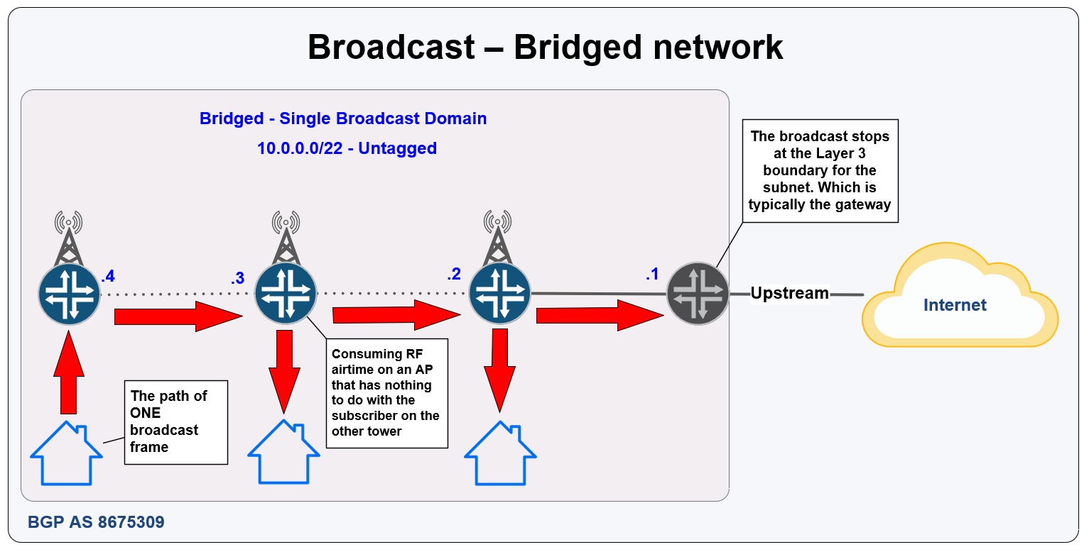
And to compare, here is the same network but routed

Answer: Patience and planning (and VLANs)
The question you’ve probably been waiting for….how do I migrate? So the dirty little secret is that you don’t have to migrate all at once.
There are a few different ways you can use VLANs to migrate the network one tower at a time.
Type 1 – Last mile back to the core – start at the very end of a chain of towers and work your way back in – one tower at a time

Type 2 – Core out to the last mile – start at the core or where your bandwidth comes in (often the same place) and work your way out – one tower at a time

Type 3 – Build L3 to a new tower from the core – If you happen to have a new tower build on deck that will directly connect back to the core (where the gateway for the bridged L3 network is), then you can build a new tower as L3. This helps to understand what’s involved and then use one of the previous two methods to migrate the rest of the network.

In order to pass VLANs and the legacy broadcast domain through the network easier, consider putting all physical links into a switch at the core and the tower instead of directly into the router.
This type of design makes operation of the WISP significantly easier as new subnets and services that are needed don’t always need a trip to the tower to add cabling.
It also makes config migration easier when upgrading the tower router by putting most of the interface references into VLANs instead of physical interfaces.
Example of a switch-centric tower design

This will help to get you started down the road to migration. Using a virtual lab like EVE-NG or GNS3 will help to understand the concepts before you deploy it in prod and is a good addition to the process.
Take your time and think through what you want to do and write down your plan – often you’ll find gaps when you create a list of steps which you can correct before migration and save time.
Good luck!
Need help with your Migration? Call the WISP experts at IP ArchiTechs
https://iparchitechs.com/contact-us/

Previously, I’ve written a number of articles that compared syntax between Cisco and MikroTik and have received some great feedback on them.
As such, I decided to begin a series on Juniper to MikroTik starting with MPLS and L3VPN interop as it related to a project I was working on last year.
In the world of network engineering, learning a new syntax for a NOS can be overwhelming if you need a specific set of config in a short timeframe. The command structure for RouterOS can be a bit challenging if you are used to Juniper CLI commands.
If you’ve worked with Juniper gear and are comfortable with how to deploy that vendor, it is helpful to draw comparisons between the commands, especially if you are trying to build a network with a MikroTik and Juniper router.
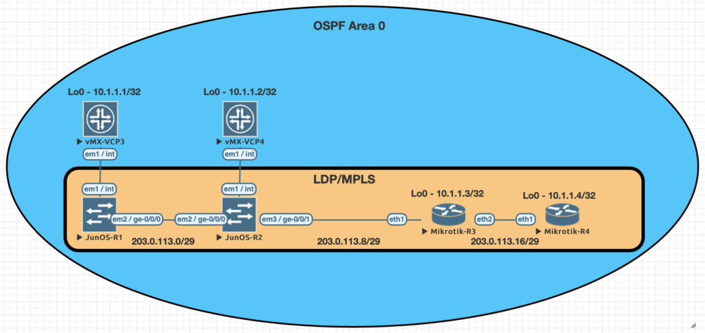
The lab consists of (3) Juniper P routers and (2) MikroTik PE routers. Although we did not get into L3VPN in this particular lab, the layout is the same.
A note on route-targets
It seems that the format of the route-target has some bearing on this being successful. Normally i’ll use a format like 8675309:1 but in this case, I had some interop issues with making that work so we used dotted decimal.
Some of the results when searching seem to suggest that platforms like Juniper and Cisco reverse the RT string in the packet while MikroTik uses it in sequential order
To work around that, the format we used was the same forwards and backwards – 1.1.1.1:1
MPLS and VPNv4 use case
MPLS is often used in service provider and data center networks to provide multi-tenancy.
VPNv4 specifically allows for separate routing tables to be created (VRFs) and advertised via BGP using the VPNv4 address family.
This address family relies on MPLS to assign a VPN label and route target as an extended community to the route which keeps it isolated from routes in other VRFs.
Practical Use
Many service provider networks rely on Juniper for the edge and core roles.
However, increasingly, ISPs want to save money on last mile and smaller aggregation points.
MikroTik is an effective choice for more simplistic MPLS capabilities as it’s inexpensive and interops with Juniper.
This creates a variety of low cost deployment options as a manged CE router, GPON aggregation in the last mile, managed CE for enterprise customers….and so on.
Command comparison
| Juniper command | MikroTik Command |
|---|---|
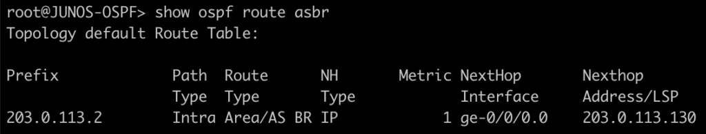
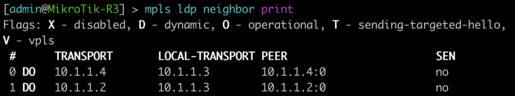
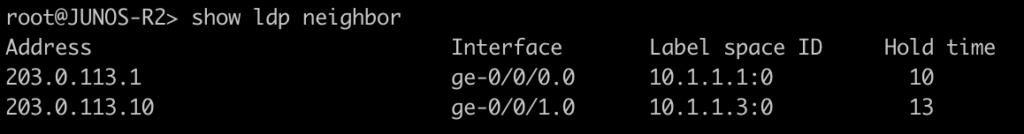
| > show ldp neighbor | mpls ldp neighbor print |
| > show mpls interface | mpls ldp interface print |
| > show route table mpls.0 | mpls forwarding-table print |
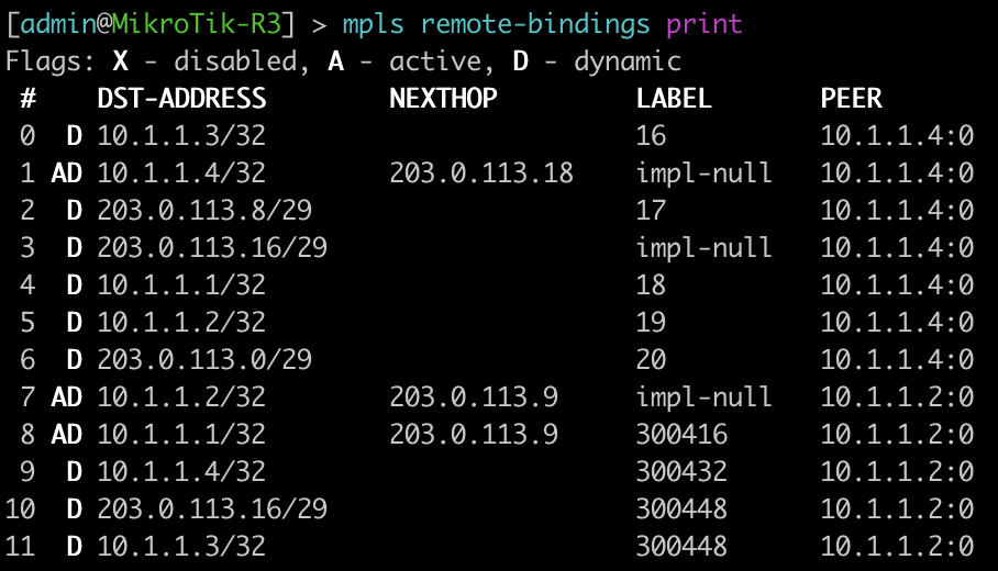
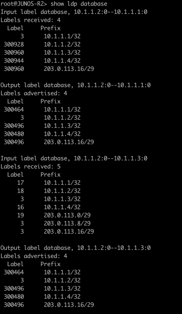
| > show ldp database | mpls remote-bindings print |
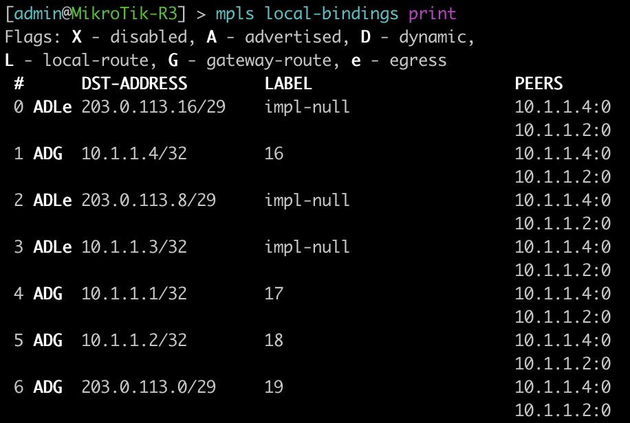
| > show ldp database | mpls local-bindings print |
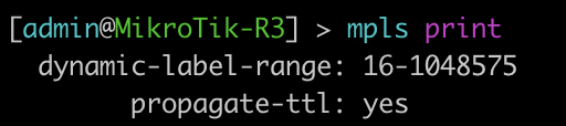
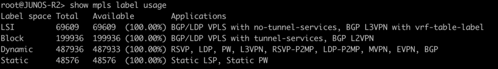
| > show mpls label usage label-range | mpls print |
| > show ldp overview | mpls ldp print |
| # set interfaces ge-0/0/0 unit 0 family mpls # set protocols mpls interface ge-0/0/0.0 # set protocols ldp interface ge-0/0/0.0 | /mpls ldp interface add interface=ether1 |
| { inherited from loopback } | /mpls ldp set enabled=yes lsr-id=10.1.1.3 |
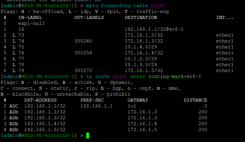
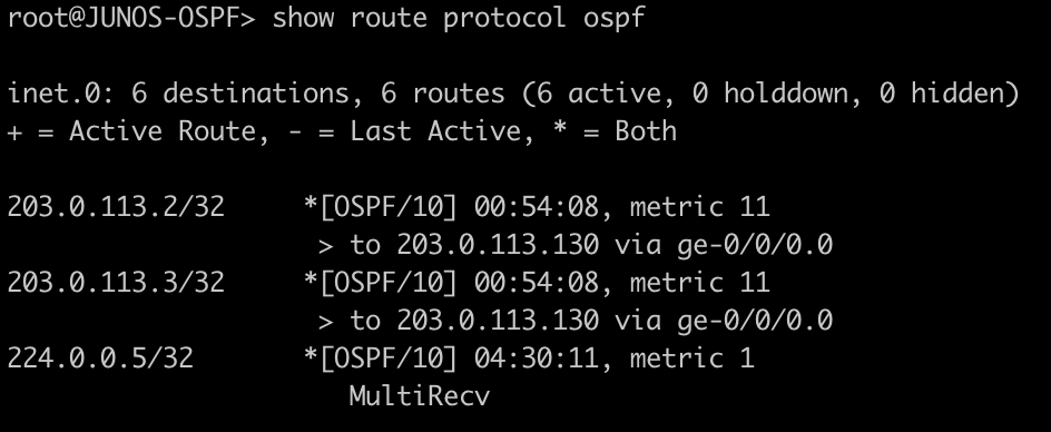
MikroTik – mpls forwarding table and vrf routes
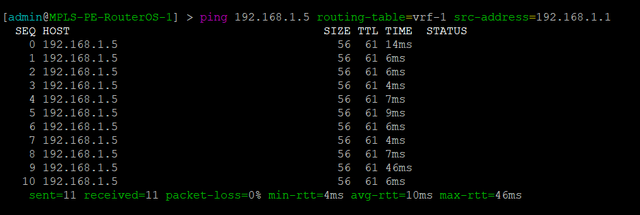
MikroTik – Ping PE2 through Juniper MPLS network
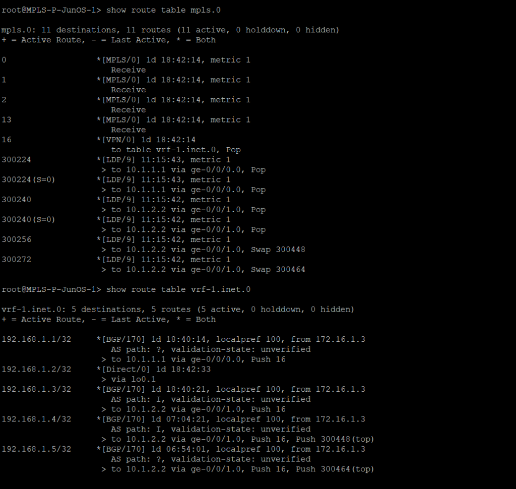
Juniper – mpls forwarding table and vrf routes
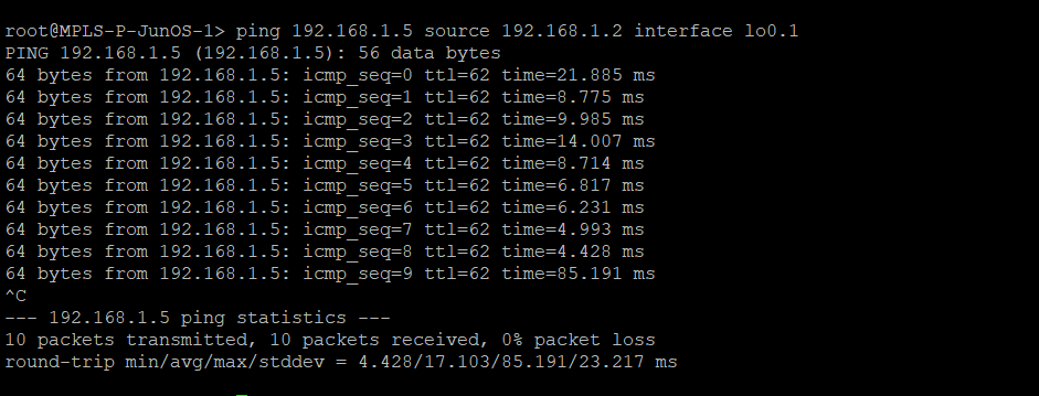
Juniper – Ping PE2 from Juniper MPLS network
MPLS-PE-RouterOS-1
/interface bridge
 add name=lo0
 add name=lo1
 /interface wireless security-profiles
 set [ find default=yes ] supplicant-identity=MikroTik
 /routing bgp instance
 set default as=8675309
 /ip address
 add address=10.1.1.1/29 interface=ether1 network=10.1.1.0
 add address=192.168.1.1 interface=lo1 network=192.168.1.1
 add address=172.16.1.1 interface=lo0 network=172.16.1.1
 /ip dhcp-client
 add disabled=no interface=ether1
 /ip route vrf
 add export-route-targets=1.1.1.1:1 import-route-targets=1.1.1.1:1 interfaces=\
     lo1 route-distinguisher=1.1.1.1:1 routing-mark=vrf-1
 /mpls ldp
 set enabled=yes lsr-id=172.16.1.1 transport-address=172.16.1.1
 /mpls ldp interface
 add interface=ether1
 /routing bgp instance vrf
 add redistribute-connected=yes routing-mark=vrf-1
 /routing bgp peer
 add address-families=ip,vpnv4 name=peer1 remote-address=172.16.1.3 remote-as=\
     8675309 update-source=lo0
 /routing ospf network
 add area=backbone network=10.1.1.0/29
 add area=backbone network=172.16.1.1/32
 /system identity
 set name=MPLS-PE-RouterOS-1
MPLS-PE-RouterOS-2
/interface bridge
 add name=lo0
 add name=lo1
 /interface wireless security-profiles
 set [ find default=yes ] supplicant-identity=MikroTik
 /routing bgp instance
 set default as=8675309
 /ip address
 add address=10.1.4.2/29 interface=ether1 network=10.1.4.0
 add address=192.168.1.5 interface=lo1 network=192.168.1.5
 add address=172.16.1.5 interface=lo0 network=172.16.1.5
 /ip dhcp-client
 add disabled=no interface=ether1
 /ip route vrf
 add export-route-targets=1.1.1.1:1 import-route-targets=1.1.1.1:1 interfaces=lo1 route-distinguisher=1.1.1.1:1 routing-mark=vrf-1
 /mpls ldp
 set enabled=yes lsr-id=172.16.1.5 transport-address=172.16.1.5
 /mpls ldp interface
 add interface=ether1
 /routing bgp instance vrf
 add redistribute-connected=yes routing-mark=vrf-1
 /routing bgp peer
 add address-families=ip,vpnv4 name=peer1 remote-address=172.16.1.3 remote-as=8675309 update-source=lo0
 /routing ospf network
 add area=backbone network=10.1.4.0/29
 add area=backbone network=172.16.1.5/32
 /system identity
 set name=MPLS-PE-RouterOS-2
MPLS-P-JunOS-1
version 14.1R1.10;
 system {
     host-name MPLS-P-JunOS-1;
     root-authentication {
         encrypted-password "$1$kj9Pva8c$R0knN0l873H.UaBUUNYA00"; ## SECRET-DATA
     }
     syslog {
         user * {
             any emergency;
         }
         file messages {
             any notice;
             authorization info;
         }
         file interactive-commands {
             interactive-commands any;
         }
     }
 }
 interfaces {
     ge-0/0/0 {
         unit 0 {
             family inet {
                 address 10.1.1.2/29;
             }
             family mpls;
         }
     }
     ge-0/0/1 {
         unit 0 {
             family inet {
                 address 10.1.2.1/29;
             }
             family mpls;
         }
     }
     lo0 {
         unit 0 {
             family inet {
                 address 172.16.1.2/32;
             }
         }
         unit 1 {
             family inet {
                 address 192.168.1.2/32;
             }
         }
     }
 }
 routing-options {
     router-id 172.16.1.2;
     route-distinguisher-id 172.16.1.2;
     autonomous-system 8675309;
 }
 protocols {
     mpls {
         traffic-engineering mpls-forwarding;
         interface ge-0/0/0.0;
         interface ge-0/0/1.0;
     }
     bgp {
         group rr {
             type internal;
             local-address 172.16.1.2;
             family inet-vpn {
                 unicast;
             }
             neighbor 172.16.1.3 {
                 peer-as 8675309;
             }
         }
     }
     ospf {
         traffic-engineering;
         area 0.0.0.0 {
             interface ge-0/0/0.0;
             interface ge-0/0/1.0;
             interface lo0.0;
         }
     }
     ldp {
         interface ge-0/0/0.0;
         interface ge-0/0/1.0;
     }
 }
 routing-instances {
     vrf-1 {
         instance-type vrf;
         interface lo0.1;
         route-distinguisher 1.1.1.1:1;
         vrf-target target:1.1.1.1:1;
         vrf-table-label;
     }
 }
MPLS-P-JunOS-2
version 14.1R1.10;
 system {
     host-name MPLS-P-JunOS-2;
     root-authentication {
         encrypted-password "$1$g6tJMNPd$f35BMnnPgit/YLshrXd/L1"; ## SECRET-DATA
     }
     services {
         ssh;
     }
     syslog {
         user * {
             any emergency;
         }
         file messages {
             any notice;
             authorization info;
         }
         file interactive-commands {
             interactive-commands any;
         }
     }
 }
 interfaces {
     ge-0/0/0 {
         unit 0 {
             family inet {
                 address 10.1.2.2/29;
             }
             family mpls;
         }
     }
     ge-0/0/1 {
         unit 0 {
             family inet {
                 address 10.1.3.1/29;
             }
             family mpls;
         }
     }
     lo0 {
         unit 0 {
             family inet {
                 address 172.16.1.3/32;
             }
         }
         unit 1 {
             family inet {
                 address 192.168.1.3/32;
             }
         }
     }
 }
 routing-options {
     router-id 172.16.1.3;
     route-distinguisher-id 172.16.1.3;
     autonomous-system 8675309;
 }
 protocols {
     mpls {
         traffic-engineering mpls-forwarding;
         interface ge-0/0/0.0;
         interface ge-0/0/1.0;
     }
     bgp {
         group rr {
             type internal;
             local-address 172.16.1.3;
             family inet-vpn {
                 unicast;
             }
             cluster 1.1.1.1;
             neighbor 172.16.1.2 {
                 peer-as 8675309;
             }
             neighbor 172.16.1.1 {
                 peer-as 8675309;
             }
             neighbor 172.16.1.3 {
                 peer-as 8675309;
             }
             neighbor 172.16.1.4 {
                 peer-as 8675309;
             }
             neighbor 172.16.1.5 {
                 peer-as 8675309;
             }
         }
     }
     ospf {
         traffic-engineering;
         area 0.0.0.0 {
             interface ge-0/0/0.0;
             interface ge-0/0/1.0;
             interface lo0.0;
         }
     }
     ldp {
         interface ge-0/0/0.0;
         interface ge-0/0/1.0;
     }
 }
 policy-options {
     policy-statement import-vrf1 {
         term import-term-connected {
             from protocol direct;
             then accept;
         }
         term term-reject {
             then reject;
         }
     }
 }
 routing-instances {
     vrf-1 {
         instance-type vrf;
         interface lo0.1;
         route-distinguisher 1.1.1.1:1;
         vrf-target target:1.1.1.1:1;
         vrf-table-label;
     }
 }
MPLS-P-JunOS-3
version 14.1R1.10;
 system {
     host-name MPLS-P-JunOS-3;
     root-authentication {
         encrypted-password "$1$kj9Pva8c$R0knN0l873H.UaBUUNYA00"; ## SECRET-DATA
     }
     syslog {
         user * {
             any emergency;
         }
         file messages {
             any notice;
             authorization info;
         }
         file interactive-commands {
             interactive-commands any;
         }
     }
 }
 interfaces {
     ge-0/0/0 {
         unit 0 {
             family inet {
                 address 10.1.3.2/29;
             }
             family mpls;
         }
     }
     ge-0/0/1 {
         unit 0 {
             family inet {
                 address 10.1.4.1/29;
             }
             family mpls;
         }
     }
     lo0 {
         unit 0 {
             family inet {
                 address 172.16.1.4/32;
             }
         }
         unit 1 {
             family inet {
                 address 192.168.1.4/32;
             }
         }
     }
 }
 routing-options {
     router-id 172.16.1.4;
     route-distinguisher-id 172.16.1.4;
     autonomous-system 8675309;
 }
 protocols {
     mpls {
         traffic-engineering mpls-forwarding;
         interface ge-0/0/0.0;
         interface ge-0/0/1.0;
     }
     bgp {
         group rr {
             type internal;
             local-address 172.16.1.4;
             family inet-vpn {
                 unicast;
             }
             neighbor 172.16.1.3 {
                 peer-as 8675309;
             }
         }
     }
     ospf {
         traffic-engineering;
         area 0.0.0.0 {
             interface ge-0/0/0.0;
             interface ge-0/0/1.0;
             interface lo0.0;
         }
     }
     ldp {
         interface ge-0/0/0.0;
         interface ge-0/0/1.0;
     }
 }
 routing-instances {
     vrf-1 {
         instance-type vrf;
         interface lo0.1;
         route-distinguisher 1.1.1.1:1;
         vrf-target target:1.1.1.1:1;
         vrf-table-label;
     }
 }
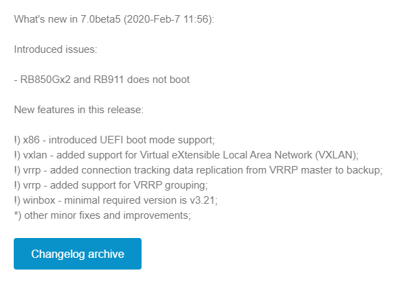
MikroTik announced VxLAN support on Valentine’s Day (Feb 14th) of 2020.
This is a significant feature addition for RouterOSv7 as it will pave the way for a number of other additions like EVPN in BGP.
It will also give MikroTik the ability to appeal to enterprises and data centers that might need cost-effective VxLAN capable devices.
Service Providers are also moving towards VxLAN as a future replacement for VPLS so this is helpful for that market as well.
Download the OVA here:
https://download.mikrotik.com/routeros/7.0beta5/chr-7.0beta5.ova
The initial release of VxLAN is based on unicast and multicast to deliver Layer 2 frames.
As there is no EVPN support, the VTEPs must be manually configured for each endpoint in a full mesh configuration.
The VxLAN interface can then be bridged to a physical ethernet port or VLAN interface to deliver the traffic to the end host.
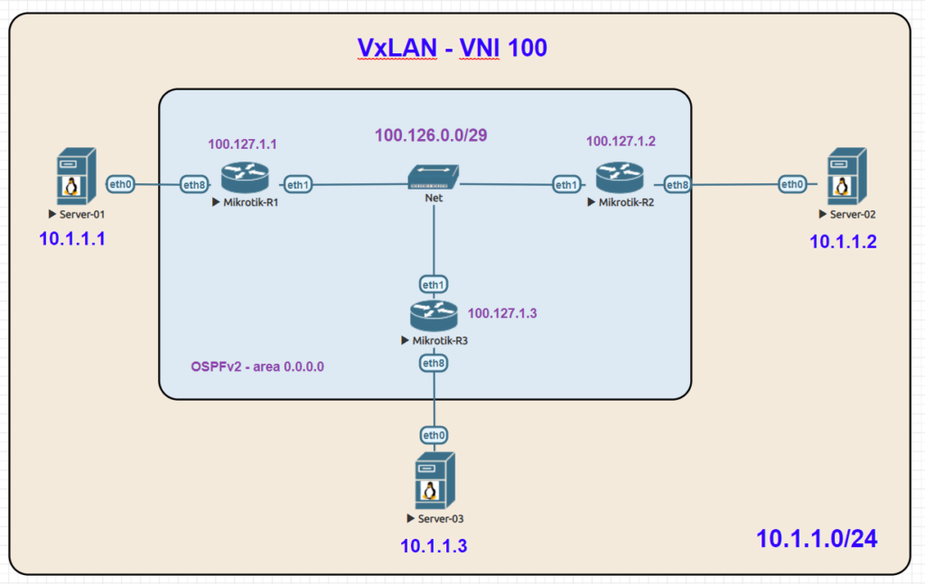
Here is an overview lab in EVE-NG with a basic setup using 3 linux servers on the same 10.1.1.0/24 subnet which is carried as an overlay by VxLAN.
VxLAN reachability for VTEPs is acheived with OSPFv2 and loopback addresses.
VNI: 100
Multicast Group: 239.0.0.1
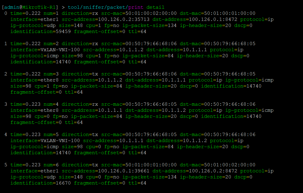
In the following packet capture, traffic to UDP port 8472 can be seen between two endpoints.
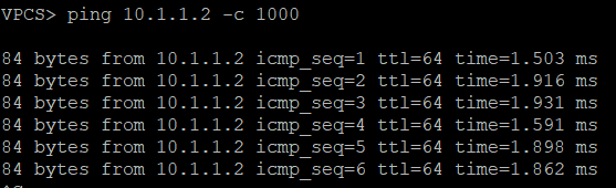
The ICMP ping test between server 1 (10.1.1.1) and server 2 (10.1.1.2) is also visible
Pings between Server 1 and Servers 2 & 3
R1
/interface bridge
 add name=Bridge-VxLAN-VNI-100
 add name=Lo0
 /interface vxlan
 add group=239.0.0.1 interface=ether1 mtu=1400 name=VxLAN-VNI-100 port=8472 vni=100
 /routing ospf instance
 add name=ospf-instance-1 router-id=100.127.1.1 version=2
 /routing ospf area
 add area-id=0.0.0.0 instance=ospf-instance-1 name=ospf-area-1
 /interface bridge port
 add bridge=Bridge-VxLAN-VNI-100 interface=ether8
 add bridge=Bridge-VxLAN-VNI-100 interface=VxLAN-VNI-100
 /interface vxlan vteps
 add interface=VxLAN-VNI-100 remote-ip=100.127.1.2
 add interface=VxLAN-VNI-100 remote-ip=100.127.1.3
 /ip address
 add address=100.127.1.1 interface=Lo0 network=100.127.1.1
 add address=100.126.0.1/29 interface=ether1 network=100.126.0.0
 /routing ospf interface
 add area=ospf-area-1 instance-id=0 network=100.126.0.0/29
 add area=ospf-area-1 instance-id=0 network=100.127.1.1
 /system identity
 set name=MikroTik-R1
R2
/interface bridge
 add name=Bridge-VxLAN-VNI-100
 add name=Lo0
 /interface vxlan
 add group=239.0.0.1 interface=ether1 mtu=1400 name=VxLAN-VNI-100 port=8472    vni=100
 /routing ospf instance
 add name=ospf-instance-1 router-id=100.127.1.2 version=2
 /routing ospf area
 add area-id=0.0.0.0 instance=ospf-instance-1 name=ospf-area-1
 /interface bridge port
 add bridge=Bridge-VxLAN-VNI-100 interface=ether8
 add bridge=Bridge-VxLAN-VNI-100 interface=VxLAN-VNI-100
 /interface vxlan vteps
 add interface=VxLAN-VNI-100 remote-ip=100.127.1.1
 add interface=VxLAN-VNI-100 remote-ip=100.127.1.3
 /ip address
 add address=100.127.1.2 interface=Lo0 network=100.127.1.2
 add address=100.126.0.2/29 interface=ether1 network=100.126.0.0
 /routing ospf interface
 add area=ospf-area-1 instance-id=0 network=100.126.0.0/29
 add area=ospf-area-1 instance-id=0 network=100.127.1.2
 /system identity
 set name=MikroTik-R2
R3
/interface bridge
 add name=Bridge-VxLAN-VNI-100
 add name=Lo0
 /interface vxlan
 add group=239.0.0.1 interface=ether1 mtu=1400 name=VxLAN-VNI-100 port=8472
     vni=100
 /routing ospf instance
 add name=ospf-instance-1 router-id=100.127.1.3 version=2
 /routing ospf area
 add area-id=0.0.0.0 instance=ospf-instance-1 name=ospf-area-1
 /interface bridge port
 add bridge=Bridge-VxLAN-VNI-100 interface=ether8
 add bridge=Bridge-VxLAN-VNI-100 interface=VxLAN-VNI-100
 /interface vxlan vteps
 add interface=VxLAN-VNI-100 remote-ip=100.127.1.1
 add interface=VxLAN-VNI-100 remote-ip=100.127.1.2
 /ip address
 add address=100.127.1.3 interface=Lo0 network=100.127.1.3
 add address=100.126.0.3/29 interface=ether1 network=100.126.0.0
 /routing ospf interface
 add area=ospf-area-1 instance-id=0 network=100.126.0.0/29
 add area=ospf-area-1 instance-id=0 network=100.127.1.3
 /system identity
 set name=MikroTik-R3
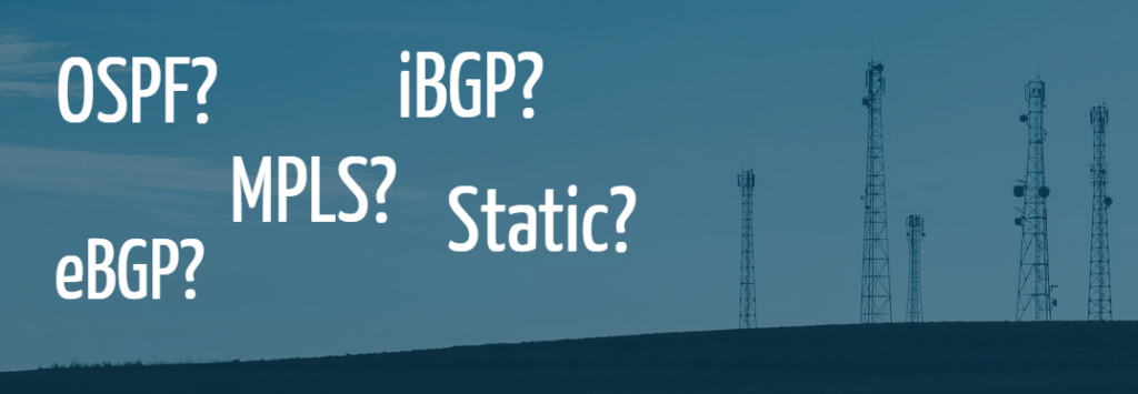
Routing is the foundation of every IP network. Even a router as small as the one in your home has a routing table and makes routing decisions.
Selecting a routing architecture is a critical but often overlooked step to ensure that a startup WISP can provide the necessary performance, scalability and resiliency to its subscribers.
This post will go through each the major design types and highlight pros/cons and when it is appropriate to use a particular routing architecture.
A note on IPv6
Dual stack is assumed in all of the designs presented. The cost of IPv4 public will continue to climb.
It’s no longer a scalable option in 2020 to build an ISP network without at least a plan for IPv6 and ideally a production implementation.
“Behind the L3 boundary, there be L2 dragons”
-ancient network proverb
Unfortunately, this is often the worst choice for all but the smallest WISPs that don’t have any plans to scale beyond 1 to 100 subscribers.
Bridged networks with one or more subnets in the same L2 broadcast domain are the most commonly deployed routing design that we see in day to day consulting working for WISPs.
Bridged networks are attractive because they require minimal networking knowledge to get up and running.
These networks have a number of limitations in scale and performance and are susceptible to loops. They also can cause RF problems with the number of broadcasts sent across all towers.
This is not an ideal choice for a startup, because it almost guarantees you’ll need a disruptive, time consuming and expensive migration once the subscriber count starts to grow.
CAUTION: “for-profit” WISPs – it is **NOT** recommended to deploy this design.
When should I deploy this network type?
Now that the “Most of you probably shouldn’t do this” warnings are out of the way… there are a few corner cases of WISPs that are for government use, non-profits, research, etc that this design can be a good fit for.
Use this design when:
Static routing is a *slight* step up from a bridged network.
With layer 3 separation between the towers, the risks of major performance issues with growth go way down.
However, the administrative burden of growth is still an issue with static routes.
This design can be used for a very simple network with only a few routers until a dynamic routing protocol can be configured.
When **NOT** to deploy this design
Note: Static routing in this context means static routes for all subnet reachability – it is not meant to include a static route (when needed) to 0.0.0.0/0 as a default on an isolated management network or for a DIA circuit
When should you deploy this design?
One of the questions we are often asked is:
Do I really need dynamic routing for a WISP that’s very small?
The answer lies in the drawing above…
it’s easy to see when looking at this drawing how complex and cumbersome static routing can become even for just 2 to 3 routers.
Open Shortest Path First or OSPF is an interior gateway protocol defined by RFC2328 for version 2 (IPv4) and RFC5340 for version 3 (IPv6).
Without going into an enormous amount of detail about the background of OSPF and IGPs in general (RIP, EIGRP, IS-IS), which is out of the scope of this post, here are a few key points about the protocol:
OSPF overview for WISPs
When **NOT** to deploy this design
When should you deploy this design?
Border Gateway Protocol or BGP is an exterior gateway protocol defined by RFC4271 for IPv4 and RFC2545 for IPv6. Although BGP started out as a protocol that was intended only for use on the Internet between public ASNs, it quickly became used in a variety of network types due to the policy options it offers. Policy describes BGP in a nutshell, it isn’t concerned with link speeds, physical topology or link state…BGP is purely focused on policy and the best path algorithm.
Multiprotocol Label Switching or MPLS is a forwarding protocol that assigns labels to routes and allows for the abstraction of different services carried in an overlay on top of the routed/label-switched core. MPLS is defined in RFC3031.
Similar to OSPF, I won’t go into an enormous amount of detail about BGP and MPLS, which is out of the scope of this post, but here are a few key points about each protocol:
BGP overview for WISPs
MPLS Overview for WISPs
BGP – More information
Network Collective
EPISODE 17 – BGP: PEERING AND REACHABILITY
MPLS – More information
MikroTik US MUM 2016 – Dallas, Texas
MPLS Overview, Design and Implementation for WISPs
When **NOT** to deploy this design
When should you deploy this design?
One of the questions we are often asked about this design is:
Should I start with all of these protocols from the very beginning. Why not just pick BGP or OSPF? Why do I need both?
The answer is twofold
This is definitely one of the newest designs we’ve worked with and deployed into production. It’s growing in popularity because using BGP for all routing actually simplifies the design quite a bit while still being able to deliver VPLS services. This design also allows for incredibly diverse traffic engineering options and full IPv4/IPv6 dual stack with BGP which is limited in some vendors.
Vendor note:
It’s worth noting that some of the limitations in the current version of MikroTik RouterOS 6.xx are what prompted this specific design
Rather than list bullet points on this topic to illustrate why and how eBGP is useful for traffic engineering in WISPs, i’ll share the following video from:
MikroTik US MUM 2017 – Denver, Colorado
When **NOT** to deploy this design
When should you deploy this design?
How to choose?
Even with the shallow depth i’ve given the routing protocols, this should still highlight the pros and cons of each design and also illustrate the role of the network vendor in supporting the necessary protocols.
Take some time (even if you have to read this article in several passes) to really understand the business case of your WISP, what you sell and what’s important for you to develop in the future.
Then evaluate the protocols needed vs. the budget required for more advanced equipment and calculate the ROI of features and agility vs. equipment/licensing cost.
Good luck!
This would probably be a relevant topic on any given day in the world of IT, but given the current global pandemic due to COVID-19 (aka coronavirus), it’s become especially important.
IT departments are scrambling to figure out how to react with capacity to connect entire companies remotely for extended periods of time.
With a traditional vendor solution that centers around a router or firewall that’s racked in a data center somewhere, this can be difficult to solve for a few reasons.
Challenges:
Luckily, IT is much more focused on software and cloud solutions these days then putting out boxes for everything.
Open source and cloud solutions when used together can provide an incredible amount of scale and performance without a long ramp up period.
We’ll be looking at the solution design below in the next few sections to explore solving the problem of remote worker VPN scale in a cost effective way.
This is an overview of a design we’ve put into production to facilitate enterprise level VPN connectivity without traditional drawbacks like scale limit, hairpinning traffic and expensive hardware and software licensing.
1000+ users – All of the solutions used in this design are open source. The ZeroTier web controller is free for deployments up to 100 endpoints and requires very minimal investment to scale to thousands of endpoints.
10,000+ users – Even 10s of thousands of endpoints would still be a very moderate cost that would mainly be centered around cloud compute fees or physical DC/Campus hypervisor capacity.
It would likely still be less than 10% of the cost of a comparable VPN + hardware box solution.
All of these components can be assembled and tested inside of a day for a handful of FW endpoints and once security policies have been reviewed and applied, full production can easily be achieved not long after that.
If you’re unfamiliar with Mesh VPNs, you’re probably not alone.
Mesh VPNs are a relatively recent concept in overlay networking that allow for connectivity directly between any two points in the mesh without hairpinning through central points like a traditional VPN concentrator.
If you want some background on different Mesh VPN solutions, check out this podcast I was recently a part of over at networkcollective.com
What Mesh VPN solutions are available?
There are a few and this isn’t an exhaustive list, but the three I hear the most chatter about are ZeroTier, Nebula and TailScale
Any of these could be used to deploy this design, but I focused on ZeroTier because it’s the most flexible to combine with traditional networking in a data center or campus using dynamic routing protocols.
ZeroTier overview
ZeroTier first got on my radar when Ethan Banks over at the Packet Pushers did a priority queue show with the founder Adam Ierymenko on the Mesh VPN solution he developed.
ZeroTier’s mission is “Global Area Networking” using a unique mix of a centralized controller and certificate based authentication of endpoints.
it’s super easy to deploy as well and can be functional between two computers, phones, etc in a matter of minutes.
Managing L2 scale
Normally, a large /16 subnet stretched across the globe would have networkers like me cringing as it’s a solution that’s often frowned upon and with good reason.
However, ZeroTier solves this in a very interesting way by managing all of the components that normally blow up L2 overlays like broadcast and multicast.
ARP is a good example – it is converted into unicast and sent to the appropriate destination as described in ZTs manual below:
Broadcast is also carried as multicast to reduce overhead. Hosts can choose to participate or block multicast based on what the host is used for.
This is how ZT scales to very large numbers in the same subnet.
And if that isn’t good enough, they also run a public network called ‘earth’ that’s one large /7, just to make sure that tens of thousands of people on one subnet won’t blow things up.
Operating system support
One of the great benefits of using ZeroTier is that it runs on practically everything including Windows, Linux, iPhone, iPad and Mac.
Just download and install the appropriate client then go to my.zerotier.com to sign up for an account and create an overlay network.
ZT Controller – managing endpoints
Once you’ve created an overlay network, ZeroTier makes it incredibly easy to manage and authorize endpoints.
Below is a screenshot of endpoints in production. Notice the last entry has IPv6 available for internet access, so ZeroTier will use that to transport the IPv4 overlay network – which is a huge benefit…the underlay IP version doesn’t matter.
This is not true in almost every other enterprise VPN solution i’ve come across – IPv4 must encapsulate in IPv4 and IPv6 must Encapsulate in IPv6.
Injecting routes
Routes are enabled to endpoints using a dynamic static route injection from the controller.
These routes show up on the host routing table to provide connectivity to endpoints within the network.
And this is what it looks like for the 10.255.x.x routes on an endpoint host to a 100.125.0.x gateway (which represents a cloud or physical DC in this network)
Security policy
ZeroTier has the ability to push flow rules to endpoints that can permit / deny or change the flow of traffic.
There are a number of ways to leverage this along with rules at the OPNSense firewall to create a security policy that is modular, effective and functional.
Example: one way to leverage flow policies is to allow RDP only on this particular ZT network by permitting TCP/3389 traffic. Combined with host authentication and firewall level permissions, access to RDP can be tightly controlled by using 3 layers of security policy.
If you’ve never used it, OPNSense is a fantastic open source firewall package.
It can be deployed from an ISO into a VM or as a bootstrap install in the cloud (I’ve successfully used AWS and Digital Ocean)
Mesh VPN and Routing
One of the intial challenges when using Mesh VPNs was to interconnect with routers and provide security policy beyond just the controller.
OPNSense has a number of packages and plugins – what initially drew me to it was the support for ZeroTier out of the box.
Installation was painless and the ZeroTier adapter was running and reachable within minutes.
Security rules
Here is a brief example of a security rule in OPNSense defining access coming from a ZeroTier remote worker subnet to a group of RDP Servers
That’s pretty much all you need to get started with connecting remote workers into the firewall.
Should you decide to force Internet access through the firewall, a NAT policy can be setup and ZeroTier can inject (or remove) a default route to the host if so desired.
The last piece to the puzzle – dynamic routing – is covered in the next section.
The final piece to glue together the Mesh VPN connectivity through the firewall is a way to dynamically advertise the VPN subnets into a router or another firewall.
FRRouting or Free Range Routing is an open source routing stack that was forked from Quagga a few years ago.
It’s a very solid and capable way to turn any linux box into a feature rich routing platform.
A quick look at the protocols supported shows a wealth of options
The plugin for OPNSense is installed in the same way as ZeroTier and is equally painless. Once intalled, a tab for routing shows up in the left hand menu.
OSPF
OSPF Configuration and creating neighbor adjacencies is very straightforward. In this network, OSPF is used to advertise loopbacks for iBGP to the DC core switch.
Here is an example from the OPNSense UI
BGP
BGP is also very easy to configure. In this example from the OPNSense UI, several ZT networks are advertised into the DC core route reflector via iBGP.
Active routes
All routes for FRRouting, including Kernel routes can be viewed from the routing diagnostics tab in OPNSense.
Here is a view of the ZeroTier 100.125.x.x routes coming from the OPNSense FW and FRRouting into the DC Core route reflector.
Running configuration
FRRouting has a running config that’s consistent with an industry standard CLI configuration.
The UI plugin will update the running config based on the web configuration, but features that aren’t supported in the UI can still be added by editing the running config.
Ultimately, this is merely a functional starting point for a corporate VPN solution.
There are so many security and networking pieces that could be added depending on an organization’s compliance and regulatory requirements.
However, the advantage of using open source components is that anything can be added to a prod build with a little time and some testing.
The key is to get a lab build and tested.
Try building out a solution with Mesh VPNs, open source firewall and routing tools and see where it takes you!
It seems like ages ago that we blocked out time in our schedules to fly to technical conferences and immerse ourselves with great people and content for an entire week.
In reality, it’s only been a few months but 2020 has made it seem like a lifetime.
However, those of us in tech are quick to adapt and virtual conferences are now a thing.
For the fixed wireless industry, in-person conferences are critical because most of the attendees are entrepreneurs.
For a small business owner in tech, going to a show is one of the best ways to evaluate content and business opportunities needed to stay competitive in a short amount of time.
Thankfully, due to some amazing efforts and collaboration in the WISP industry – led by Preseem and supported by WISPA, we are about to kick off the first virtual conference for the fixed wireless industry at 10 AM Eastern on July 28th, 2020.
An enormous amount of work has gone into planning and preparation to replicate the experience of an in-person technical conference as much as possible.
Kick off the registration process by visiting: https://wispvirtualsummit2020.com/
First you’ll need to get registered by signing up and paying a very modest $25 registration fee – probably the least expensive tech conference you’ll ever attend.
My company, IP ArchiTechs is a platinum sponsor and you can use our discount code of IPARCHITECHS25 to save a few bucks before completing your registration.
When you first sign into the conference site at https://wispvirtualsummit2020.com/ you’ll see a page similar to the picture above.
This is the main event area online where you can browse to virtual vendor booths, check the event schedule with speakers and live streams as well as earn points for prizes throughout the day.
There are chat areas, a social media wall and group discussions.
There is a great how-to video that’s very brief to quickly orient you on how to navigate the conference platform. Take a few minutes and check it out
Looking at the menu on the left, you’ll see all of the sessions planned for the day with times and links.
I’ll be talking about Overlays/Underlays for WISPs in the Core and Backhaul Network: Designing in 2020 session at 2:45 PM Eastern Time.
This session will be helpful if you want to learn more about technologies like MPLS, Segment Routing, VxLAN, VPLS and their role in a WISP network.
WISPA Keynote
The sessions will kick off with Claude Aiken, the President of WISPA giving a keynote on WISPs during the COVID-19 era at 10 AM Eastern time.
Visit the virtual booth for each vendor to get contact information, a brief description of the company and videos to get an idea of how each company can benefit you and your WISP.
Just as it would be at an in-person conference, the booth will be staffed via chat and you can interact with people at the virtual booth in real time.
I’ll be online all day along with the rest of the team at IP ArchiTechs if you’re interested in chatting about network design, operations or whatever….give us a shout.
Hope to see you there!
When MikroTik announced the CRS3xx series switches a few years ago, one of the most exciting aspects of that news release was the prospect of L3 forwarding in hardware on very inexpensive devices.
A quick review of the Marvell Prestera ASIC family showed a number of advanced routing, switching, MPLS and VxLAN capabilites.
Fast forward to 2020, where MikroTik has started to enable some of those features in RouterOS v7 beta.
Now we can finally take some of the CRS3xx switches and test their capabilities with L3 forwarding performance in hardware
Before getting into the testing, it’s probably helpful to review some of the basic specs and capabilities of the CRS3xx switch line.
Here is a chart from MikroTik that outlines ACL rule count, Unicast FDB entries and MTU size.
CRS 3xx model comparison
MIkroTik has been working on the development of the features listed below to offload into hardware.
For the tests in this article, we’ll be using IPv4 Unicast and Inter-VLAN routing.
Supported feature list
Currently, the following switches are supported.
For the testing in this article, we are using the CRS317-1G-16S+
Switches supported by 7.1beta2
The physical setup for testing is fairly straightforward.
The logical setup is also very straightforward
MikroTik Configuration
/interface bridge
add mtu=9216 name=bridge1 vlan-filtering=yes
add name=lo0
/interface ethernet
set [ find default-name=sfp-sfpplus15 ] comment="Proxmox - ens2f0" l2mtu=10218 mtu=9216
set [ find default-name=sfp-sfpplus16 ] comment="Proxmox - ens2f1" l2mtu=10218 mtu=9216
/interface vlan
add interface=bridge1 mtu=9216 name=vlan103 vlan-id=103
add interface=bridge1 mtu=9216 name=vlan104 vlan-id=104
/interface ethernet switch
set 0 l3hw=yes
/ip pool
add name=dhcp_pool0 ranges=10.255.34.11-10.255.34.254
add name=dhcp_pool1 ranges=10.255.35.2-10.255.35.254
/ip dhcp-server
add address-pool=dhcp_pool0 disabled=no interface=vlan103 name=dhcp1
add address-pool=dhcp_pool1 disabled=no interface=vlan104 name=dhcp2
/ip vrf
add list=all name=main
/interface bridge port
add bridge=bridge1 interface=sfp-sfpplus15 pvid=103
add bridge=bridge1 interface=sfp-sfpplus16 pvid=104
/interface bridge vlan
add bridge=bridge1 tagged=bridge1 untagged=sfp-sfpplus15 vlan-ids=103
add bridge=bridge1 tagged=bridge1 untagged=sfp-sfpplus16 vlan-ids=104
/ip address
add address=10.255.34.1/24 interface=vlan103 network=10.255.34.0
add address=10.255.35.1/24 interface=vlan104 network=10.255.35.0
/ip dhcp-server network
add address=10.255.34.0/24 dns-server=9.9.9.9 gateway=10.255.34.1
add address=10.255.35.0/24 dns-server=9.9.9.9 gateway=10.255.35.1
CPU – 0% to 3%
CRS 317 – interface sfp-sfpplus15
iperf3 results
CPU – 0% to 3%
CRS 317 – interface sfp-sfpplus15
iperf3 results
CPU – 0% to 3%
CRS 317 – interface sfp-sfpplus15
iperf3 results
The initial results are very promising. Getting close to 10G sustained L3 throughput using an ASIC on a device that lists for $399 USD is unheard of.
The most noteworthy items for improvement are the number of TCP retransmits in the iperf testing and the speed reduction as the MTU is reduced.
Normally, most ASIC based platforms will push 96 bytes through as fast as 1500 bytes. The retransmits suggest that more work is needed in the way RouterOS interfaces with the switching buffers for L3 HW offload
This is also on a beta version of RouterOS that will still go through many revisions before going into prod so I would expect to see the performance to improve as the code matures.
All things considered though, things are looking great to take the CRS3xx series and be able to deploy them as a true L3 switch in prod sometime in 2021.
If you missed it, take a look at MikroTik’s video on RouterOS v7 routing performance and changes.
One of the long awaited benefits of RouterOS version 7 is a new routing protocol stack that enables new capabilities and fixes limitations in RouterOSv6 caused by the use of a very old Linux kernel.
The new routing stack in v7 has created quite a buzz in the MikroTik community as lab tests have shown that it’s significantly more efficient in processing large numbers of BGP routes.
The ability to use MikroTik’s new generation of CCR routers with ARM64 to quickly process BGP routes is a blog post all to itself and we’ll tackle that in the future – however, the information below provides a quick look into the performance comparison between ROS v6 and v7.
The new routing stack also paves the way to add a number of features that have been needed for a long time like RPKI and large community support.
Using a lab based on EVE-NG, we’ll take a look at configuration changes and iBGP using the IPv6 AFI with OSPFv3 as the IGP for loopback/next hop reachability. Prior to 7.1beta2, this has been nonfunctional for years due to routing recursion limitations.
For the most up to date information about features and capabilities in v7, MikroTik created a page that tracks feature status across the different beta releases
https://help.mikrotik.com/docs/display/ROS/v7+Routing+Protocol+Status
ROS Version: 7.1beta2 (7.1beta3 was released just before I published this – at some point i’ll update with testing on beta3)
Network Modeling: EVE-NG Pro
One of the biggest changes in OSPF for both version 2 (IPv4) and version 3 (IPv6) is the consolidation of menus into a single location for OSPF configuration.
In ROSv7, all configuration occurs under /routing/ospf/ and instances can be created for v2 or v3.
Change from ROSv6: OSPF Menu options have changed in ROSv7, this is partly due to combining OPSFv2 and OSPFv3 into a single configuration framework.
OSPF command options in ROSv6 for OSPFv2 and OSPFv3
OSPF command options in ROSv7 for both versions of OSPF
Change from ROSv6: There is a new flag in the IPv6 routing table for ECMP and no flag for RIP
When looking at the new output for the routing table, a few things stand out. ECMP has a new flag using the “+” symbol to denote two or more equal paths.
ECMP in IPv6 is a feature limitation that RouterOSv6 had and this will make it easier to deploy IPv6 networks with MikroTik.
RIP or Routing Internet Protocol is missing from the routing flags. It’s unclear at this point whether RIPv2 or RIP-NG will make it into RouterOSv7 since it’s not used very often anymore in prod networks.
Correcting issues with recursive routing in IPv6.
Being able to use recursive routing for advertising loopbacks and using iBGP with IPv6 has been a limitation of ROSv6 for a long time due to the older linux kernel in use.
Now that ROSv7 has added the initial support for OSPF and BGP, we are able to test IPv6 routing recursion.
Here is a test from PE-1 to PE-2 (2001:db8:101::12) using iBGP
It works!
Change from ROSv6: Using filters in OSPF
One of the first major challenges I had to solve when working with ROSv7 was figuring out why every route available became advertised into OSPF.
At first it looked like a bug, but when I dug deeper, I came across this snippet in the new MikroTik help docs
ROSv7 Basic Routing Examples – RouterOS – MikroTik Documentation
As it turns out, the default behavior is to advertise all routes in the absence of an outbound filter.
The next challenge was figuring out the new filtering syntax.
/routing filter rule
add chain=OSPF-permit-only-configured
/routing filter select-rule
add chain=OSPF-permit-only-configured_select do-where=\
OSPF-permit-only-configured
In order to use a rule in ROSv7, the “/routing filter select-rule” command must be used and reference the filter rule or no action will be taken.
In the example above, only interfaces that have been configured for OSPF will be advertised.
OSPF Config
Here is a summary of the OSPF configuration from the PE-1 router
/routing ospf instance
add name=IPv6 out-filter=OSPF-permit-only-configured_select router-id=\
100.127.0.11 version=3
/routing ospf area
add area-id=0.0.0.0 instance=IPv6 name=area-0
/routing filter rule
add chain=OSPF-permit-only-configured
/routing filter select-rule
add chain=OSPF-permit-only-configured_select do-where=\
OSPF-permit-only-configured
/routing ospf interface
add area=area-0 network=ether1 network-type=point-to-point
add area=area-0 network=ether2 network-type=point-to-point
add area=area-0 network=lo-ospf network-type=broadcast
As with OSPF, BGP saw a change in menu structure.
In ROSv7, BGP configuration has been revamped and is much closer to the style of configuration that Cisco/Juniper use with config elements that can be nested and reused.
Considering all the work that’s being done to improve full table convergence time on ROSv7, this change is a step in the right direction to allow MikroTik to compete with larger network vendors in the area of peering and transit.
Change from ROSv6: BGP Menu options have changed in ROSv7 to accommodate new features like Templates and RPKI
BGP command options in ROSv6
BGP command options in ROSv7
New Feature: BGP Roles
This is a new capability in BGP as of July 2020 and MikroTik was one of the first to have it implemented.
draft-ietf-idr-bgp-open-policy-13 – Route Leak Prevention using Roles in Update and Open messages
The main goal is to classify peerings into different roles that prevent inadvertent route leaks by adopting some basic filtering policies as a component of the role assignment.
Acceptable pairings are:
Here is an example of role types in ROSv7
This is an overview of how the roles deal with route advertisements and filtering.
New Feature: BGP Templates
BGP Templates allow specific settings for a peer connection to be reused in the connection configuration.
This saves quite a bit of time when deploying a large number of iBGP peerings, transit peerings, IX peerings, etc
Options available to set in templates
Here is a BGP template as configured in the lab for this post. The template is referenced by the connection config (aka peer config)
/routing bgp template
add address-families=ipv6 as=8675309 instance=bgp name=ASN-8675309

/routing bgp connection
add local.address=2001:db8:127::11 .role=ibgp-rr-client remote.address=\
2001:db8:127::1 .as=8675309 template=ASN-8675309
New Feature: iBGP ECMP for IPv6
ECMP has been working in ROSv6 for a ling time, but due to kernel limitations, it hasn’t been available in IPv6 due to the problems in routing recursion and making iBGP operational.
Now that routing recursion is fixed for IPv6, ECMP is possible.
ECMP capable IPV6 routes in BGP noted by the new “+” symbol in the routing table for ECMP.
Here is an example of a traceroute to the same prefix that’s using two different paths with ECMP.
BGP Configuration
Here is an overview of the BGP configuration for PE-1
/routing instance
add id=100.127.0.11 name=bgp
/routing bgp template
add address-families=ipv6 as=8675309 instance=bgp name=ASN-8675309
/routing bgp connection
add local.address=2001:db8:127::11 .role=ibgp-rr-client remote.address=\
2001:db8:127::1 .as=8675309 template=ASN-8675309
All Lab configs for ROSv7 are listed below (tested in 7.1beta2)
PE-1
/interface bridge
add name=lo-bgp
add name=lo-ospf
/interface wireless security-profiles
set [ find default=yes ] supplicant-identity=MikroTik
/ip vrf
add list=all name=main
/routing instance
add id=100.127.0.11 name=bgp
/routing bgp template
add address-families=ipv6 as=8675309 instance=bgp name=ASN-8675309
/routing ospf instance
add name=IPv6 out-filter=OSPF-permit-only-configured_select router-id=\
    100.127.0.11 version=3
/routing ospf area
add area-id=0.0.0.0 instance=IPv6 name=area-0
/ip dhcp-client
add disabled=no interface=ether1
/ipv6 address
add address=2001:db8:126:1::2/126 advertise=no interface=ether1
add address=2001:db8:127::11/128 advertise=no interface=lo-ospf
add address=2001:db8:101::11/128 advertise=no interface=lo-bgp
add address=2001:db8:126:3::2/126 advertise=no interface=ether2
add address=2001:db8:a1a::1 interface=ether4
/routing bgp connection
add local.address=2001:db8:127::11 .role=ibgp-rr-client remote.address=\
    2001:db8:127::1 .as=8675309 template=ASN-8675309
/routing filter rule
add chain=OSPF-permit-only-configured
/routing filter select-rule
add chain=OSPF-permit-only-configured_select do-where=\
    OSPF-permit-only-configured
/routing ospf interface
add area=area-0 network=ether1 network-type=point-to-point
add area=area-0 network=ether2 network-type=point-to-point
add area=area-0 network=lo-ospf network-type=broadcast
/system identity
set name=PE-1
CORE-1
/interface bridge
add name=lo-bgp
add name=lo-ospf
/interface wireless security-profiles
set [ find default=yes ] supplicant-identity=MikroTik
/ip vrf
add list=all name=main
/routing instance
add id=100.127.0.1 name=bgp
/routing bgp template
add address-families=ipv6 as=8675309 instance=bgp name=ASN-8675309
/routing ospf instance
add name=IPv6 router-id=100.127.0.1 version=3
/routing ospf area
add area-id=0.0.0.0 instance=IPv6 name=area-0
/ip dhcp-client
add disabled=no interface=ether1
/ipv6 address
add address=2001:db8:126:1::1/126 advertise=no interface=ether1
add address=2001:db8:127::1/128 advertise=no interface=lo-ospf
add address=2001:db8:126:2::1/126 advertise=no interface=ether2
add address=2001:db8:126:3::1/126 advertise=no interface=ether3
add address=2001:db8:101::1/128 advertise=no interface=lo-bgp
add address=2001:db8:126:4::1/126 advertise=no interface=ether4
/routing bgp connection
add listen=yes local.address=2001:db8:127::1 .role=ibgp-rr remote.address=\
    2001:db8:127::11 template=ASN-8675309
add listen=yes local.address=2001:db8:127::1 .role=ibgp-rr remote.address=\
    2001:db8:127::12 template=ASN-8675309
/routing filter rule
add chain=OSPFv3-in match-prfx-value=dst<equal>2001:db8:101::/128
add chain=OSPFv3-in match-prfx-value=dst<equal>2001:db8:101::/128
/routing ospf interface
add area=area-0 network=ether1 network-type=point-to-point
add area=area-0 network=ether2 network-type=point-to-point
add area=area-0 network=ether3 network-type=point-to-point
add area=area-0 network=lo-ospf network-type=broadcast
add area=area-0 network=ether4 network-type=point-to-point
/system identity
set name=CORE-1
PE-2
/interface bridge
add name=lo-bgp
add name=lo-ospf
/interface wireless security-profiles
set [ find default=yes ] supplicant-identity=MikroTik
/ip vrf
add list=all name=main
/routing instance
add id=100.127.0.12 name=bgp
/routing bgp template
add address-families=ipv6 as=8675309 instance=bgp name=ASN-8675309
/routing ospf instance
add name=IPv6 out-filter=OSPF-permit-only-configured_select router-id=\
    100.127.0.12 version=3
/routing ospf area
add area-id=0.0.0.0 instance=IPv6 name=area-0
/ip dhcp-client
add disabled=no interface=ether1
/ipv6 address
add address=2001:db8:126:2::2/126 advertise=no interface=ether1
add address=2001:db8:127::12/128 advertise=no interface=lo-ospf
add address=2001:db8:101::12/128 advertise=no interface=lo-bgp
add address=2001:db8:a1b::1 interface=ether4
add address=2001:db8:126:4::2/126 advertise=no interface=ether2
/routing bgp connection
add local.address=2001:db8:127::12 .role=ibgp-rr-client remote.address=\
    2001:db8:127::1 .as=8675309 template=ASN-8675309
/routing filter rule
add chain=OSPF-permit-only-configured
/routing filter select-rule
add chain=OSPF-permit-only-configured_select do-where=\
    OSPF-permit-only-configured
/routing ospf interface
add area=area-0 network=ether1 network-type=point-to-point
add area=area-0 network=lo-ospf network-type=broadcast
add area=area-0 network=ether2 network-type=point-to-point
/system identity
set name=PE-2
In the world of network engineering, learning a new syntax for a NOS can be daunting if you need a specific config quickly. Juniper is a popular option for service providers/data centers and is widely deployed across the world.
This is a continuation of the Rosetta stone for network operating systems series. We’ll be working through several protocols over series of posts to help you quickly move between different environments.
While many commands have almost the exact same information, others are as close as possible. Since there isn’t always an exact match, sometimes you may have to run two or three commands to get the information needed.
We conducted all of this testing utilizing EVE-NG and the topology seen below.
| Juniper Command | MikroTik Command |
|---|---|
| show bgp summary | routing bgp peer print brief |
| show bgp neighbor | routing bgp peer print status |
| show route advertising-protocol bgp 172.31.254.2 | routing bgp advertisements print peer=peer_name |
| show route receive-protocol bgp 172.31.254.2 | ip route print where received-from=peer_name |
| show route protocol bgp | ip route print where bgp=yes |
| clear bgp neighbor 172.31.254.2 soft-inbound | routing bgp peer refresh peer_name |
| clear bgp neighbor 172.31.254.2 soft | routing bgp peer resend peer_name |
| set routing-options autonomous-system 1 | /routing bgp instance set default as=2 |
| set protocols bgp group EBGP type external set protocols bgp group EBGP peer-as 2 set protocols bgp group EBGP neighbor 172.31.254.2 | /routing bgp peer add name=PEER-1 remote-address=172.31.254.1 remote-as=1 |
| set policy-options policy-statement REDIS-CONNECTED term 1 from protocol direct set policy-options policy-statement REDIS-CONNECTED term 1 then accept set protocols bgp group EBGP export REDIS-CONNECTED | /routing bgp network add network=100.89.88.0/24 add network=100.89.87.0/24 add network=100.89.86.0/24 |
| set routing-options static route 0.0.0.0/0 discard set protocols bgp group EBGP export SEND-DEFAULT set policy-options policy-statement SEND-DEFAULT term 1 from protocol static set policy-options policy-statement SEND-DEFAULT term 1 from route-filter 0.0.0.0/0 exact set policy-options policy-statement SEND-DEFAULT term 1 then accept | /routing bgp peer add default-originate-always name=PEER-1 remote-address=172.31.254.1 remote-as=1 |
This is a quick way to get a list of the peers/ASN and their status
[admin@MIKROTIK-BGP] > routing bgp peer print brief
root@JUNOS-BGP> show bgp summary
This next command will show you more information about a peer. In this case we did not specify the peer as there is only one. On a peering router with multiple peers it is recommended to look only at specific peer information to not be overwhelmed with irrelevant information.
[admin@MIKROTIK-BGP] > routing bgp peer print status
root@JUNOS-BGP> show bgp neighbor
The next command allows you to see the prefixes that are sent to your peer as well as the next-hop associated with it.
[admin@MIKROTIK-BGP] > routing bgp advertisements print peer=PEER-1
root@JUNOS-BGP> show route advertising-protocol bgp 172.31.254.2
This next one will show you what routes were received from the peer and the next-hop you will advertise.
[admin@MIKROTIK-BGP] > ip route print where received-from=PEER-1
root@JUNOS-BGP> show route receive-protocol bgp 172.31.254.2
Here we will see the BGP prefixes that are in the routing table – both active and not. On junOS you will see the count for hidden routes in the output but you will not see the hidden entries. This will require the use of “show route protocol bgp hidden” to see the hidden entries. On mikrotik you will see this type of route in the route table as inactive.
[admin@MIKROTIK-BGP] > ip route print where bgp=yes
root@JUNOS-BGP> show route protocol bgp
Configure BGP instance, peering, and originate a default route.
Here is a very basic BGP peering configuration to establish a peer, advertise a few routes, and originate a default route.
Let’s look at some of the differences in the configuration.
It’s worth noting that everything in CAPS was manually defined .
On junOS there is no concept of the “network” command that you might see in MikroTik or Cisco.
To accomplish the same functionality in this example I used a policy-statement named REDIS-CONNECTED that matched any connected route for redistribution.
This is then applied as an export statement into the EBGP peer group. Likewise, there is not a construct for “default-originate”. In order to accomplish the same functionality, we created a static route to discard and exported this to the EBGP peer.
MikroTik BGP Configuration
/routing bgp instance
set default as=2
/routing bgp network
add network=100.89.88.0/24
add network=100.89.87.0/24
add network=100.89.86.0/24
/routing bgp peer
add default-originate=always name=PEER-1 remote-address=172.31.254.1 remote-as=1
Juniper BGP Configuration
set interfaces lo0 unit 0 family inet address 100.99.98.1/24
set interfaces lo0 unit 0 family inet address 100.99.97.1/24
set interfaces lo0 unit 0 family inet address 100.99.96.1/24
set routing-options static route 0.0.0.0/0 discard
set routing-options autonomous-system 1
set protocols bgp group EBGP type external
set protocols bgp group EBGP export REDIS-CONNECTED
set protocols bgp group EBGP export SEND-DEFAULT
set protocols bgp group EBGP peer-as 2
set protocols bgp group EBGP neighbor 172.31.254.2
set policy-options policy-statement REDIS-CONNECTED term 1 from protocol direct
set policy-options policy-statement REDIS-CONNECTED term 1 then accept
set policy-options policy-statement SEND-DEFAULT term 1 from protocol static
set policy-options policy-statement SEND-DEFAULT term 1 from route-filter 0.0.0.0/0 exact
set policy-options policy-statement SEND-DEFAULT term 1 then accept
More to come
There are so many commands to consider for BGP, we probably could have added close to 100, but we decided to list the commands we use most often to start with and will be adding to the list of BGP commands as well as other like OSPF, MPLS, and VLANs in future posts.
In the world of network engineering, learning a new syntax for a NOS can be daunting if you need a specific config quickly. Juniper is a popular option for service providers/data centers and is widely deployed across the world.
This is a continuation of the Rosetta stone for network operating systems series. In this portion of the series we will be covering Open Shortest Path First, OSPF, version 2 which is a popular interior gateway protocol (IGP).
You can find the first article of the series Juniper to Mikrotik – BGP Commands here.
While many commands have almost the exact same information, others are as close as possible. Since there isn’t always an exact match, sometimes you may have to run two or three commands to get the information needed.
We conducted all testing on EVE-NG utilizing the topology seen below.
| JunOS Command | MikroTik Command |
|---|---|
| show ospf neighbor | routing ospf neighbor print |
| show ospf interface | routing ospf interface print |
| show ospf overview brief | routing ospf instance print detail |
| show ospf database | routing ospf lsa print |
| show route protocol ospf | ip route print where ospf=yes |
| show ospf route abr | routing ospf area-border-router print |
| show ospf route asbr | routing ospf as-border-router print |
| edit protocols ospf | /routing ospf instance |
| set routing-options router-id 203.0.113.1 | /routing ospf instance set 0 router-id=203.0.113.2 |
| set protocols ospf area 0.0.0.0 interface lo0.0 | /routing ospf network add area=backbone network=203.0.113.2/32 |
| set protocols ospf area 0.0.0.0 interface ge-0/0/0.0 | /routing ospf network add area=backbone network=203.0.113.128/29 |
| set protocols ospf area 0.0.0.0 interface ge-0/0/0.0 interface-type p2p set protocols ospf area 0.0.0.0 interface ge-0/0/0.0 hello-interval 1 set protocols ospf area 0.0.0.0 interface ge-0/0/0.0 dead-interval 4 | /routing ospf interface add dead-interval=4s hello-interval=1s interface=ether1 network-type=point-to-point |
This first command will show you all of the routers you have an OSPF neighbor adjacency with.
[admin@MIKROTIK-OSPF] > routing ospf neighbor print
root@JUNOS-OSPF> show ospf neighbor
This next command lists all of the interface enabled for OSPF as well as some basic information such as cost, priority, and network type. Juniper displays slightly different information such as area, DR info, and number of neighbors. Juniper does not have the concept of a network statement so interfaces explicitly configured for OSPF will appear here. You can optionally add the detail command on JunOS for more information.
[admin@MIKROTIK-OSPF] > routing ospf interface print
root@JUNOS-OSPF> show ospf interface
This command will list all of the details regarding the OSPF instances running on the router.
[admin@MIKROTIK-OSPF] > routing ospf instance print
root@JUNOS-OSPF> show ospf overview brief
This command lists all of the OSPF LSAs as well as some details about them.
[admin@MIKROTIK-OSPF] > routing ospf lsa print
root@JUNOS-OSPF> show ospf database
This next command will show all of the OSPF routes in the routing table.
[admin@MIKROTIK-OSPF] > ip route print where ospf=yes
root@JUNOS-OSPF> show route protocol ospf
This next set of commands will show you the area-border-routers or autonomous-system-boundary routers. We injected a connected route into OSPF to generate a type-5 LSA for an external route.
[admin@MIKROTIK-OSPF] > routing ospf area-border-router print
[admin@MIKROTIK-OSPF] > routing ospf as-border-router print
root@JUNOS-OSPF> show ospf route abr
root@JUNOS-OSPF> show ospf route asbr
Mikrotik OSPF configuration
/interface bridge
add name=Loopback0
add name=Loopback1
add name=Loopback2
/interface wireless security-profiles
set [ find default=yes ] supplicant-identity=MikroTik
/routing ospf area
add area-id=0.0.0.51 name=Area51
/routing ospf instance
set [ find default=yes ] redistribute-connected=as-type-1 router-id=203.0.113.2
/ip address
add address=203.0.113.2 interface=Loopback0 network=203.0.113.2
add address=203.0.113.3 interface=Loopback1 network=203.0.113.3
add address=203.0.113.4 interface=Loopback2 network=203.0.113.4
add address=203.0.113.130/29 interface=ether1 network=203.0.113.128
/ip dhcp-client
add dhcp-options=hostname,clientid disabled=no interface=ether1
/routing ospf interface
add dead-interval=4s hello-interval=1s interface=ether1 network-type=point-to-point
/routing ospf network
add area=backbone network=203.0.113.2/32
add area=backbone network=203.0.113.128/29
add area=Area51 network=203.0.113.3/32
/system identity
set name=MIKROTIK-OSPF
Juniper OSPF configuration
set interfaces ge-0/0/0 unit 0 family inet address 203.0.113.129/29
set interfaces lo0 unit 0 family inet address 203.0.113.1/32
set routing-options router-id 203.0.113.1
set protocols ospf area 0.0.0.0 interface ge-0/0/0.0 interface-type p2p
set protocols ospf area 0.0.0.0 interface ge-0/0/0.0 hello-interval 1
set protocols ospf area 0.0.0.0 interface ge-0/0/0.0 dead-interval 4
set protocols ospf area 0.0.0.0 interface lo0.0 passive
This article covered some of basic and common OSPF commands. Check back in the future for examples of more advanced features and capabilities. Also stay tuned for our upcoming Juniper to MikroTik MPLS command translation.
In the world of network engineering, learning a new syntax for a NOS can be daunting if you need a specific config quickly. Juniper is a popular option for service providers/data centers and is widely deployed across the world.
This is a continuation of the Rosetta stone for network operating systems series. In this article we will be covering multi-protocol label switching (MPLS) using label distribution protocol (LDP). We are sticking with LDP as MikroTik does not have wide support for RSVP-TE.
You can find the first two articles of the series here:
Juniper to MikroTik – BGP commands
Juniper to MikroTik – OSPF commands
While many commands have almost the exact same information, others are as close as possible. Since there isn’t always an exact match, sometimes you may have to run two or three commands to get the information needed.
We conducted utilized EVE-NG for all of the testing with the topology seen below.
| Juniper Command | MikroTik Command |
|---|---|
| show ldp neighbor | mpls ldp neighbor print |
| show ldp interface | mpls ldp interface print |
| show route forwarding-table family mpls | mpls forwarding-table print |
| show ldp database | mpls remote-bindings print |
| show ldp database | mpls local-bindings print |
| show mpls label usage | mpls print |
| set interfaces ge-0/0/0 unit 0 family mpls set protocols ldp interface ge-0/0/0.0 | /mpls ldp interface add interface=ether1 |
| set routing-options router-id 10.1.1.1 | /mpls ldp set enabled=yes lsr-id=10.1.1.3 |
This first command will show you some basic information about your MPLS LDP neighbors. On juniper you can add the keyword detail to the end for additional information on the neighbors.
[admin@MikroTik-R3] > mpls ldp neighbor print
root@JUNOS-R2> show ldp neighbor
This command will list all of the interfaces that are currently enabled for LDP.
[admin@MikroTik-R3] > mpls ldp interface print
root@JUNOS-R2> show ldp interface
Use this command to display the MPLS forwarding table which shows what labels are assigned, the interface used and the next-hop. It will also tell you the action taken such as pop, swap, or push.
[admin@MikroTik-R3] > mpls forwarding-table print
root@JUNOS-R2> show route forwarding-table family mpls
The next two commands will be combined since juniper only has one command to be equivalent to mikrotiks output. This is will show the advertised and received labels for all of the prefixes known to LDP as well as the label associated with it and where it was learned from. On JunOS you will notice label 3. This is juiper’s method to signal implicit null and request label popping by the downstream router.
[admin@MikroTik-R3] > mpls remote-bindings print
[admin@MikroTik-R3] > mpls local-bindings print
root@JUNOS-R2> show ldp database
This last command will show the label ranges and what they are used for.
[admin@MikroTik-R3] > mpls print
root@JUNOS-R2> show mpls label usage
root@JUNOS-R1# show | display set
set version 18.2R1.9
set system root-authentication encrypted-password "$6$iCt/DOMc$lQFrIQdrjot1m0lIY5A2eUaOmat87oAqbNZWd/3KPij2QWTlBQEyYlVbb1/emd2N9VKN6NL0olk.kJK7mLcgM0"
set system host-name JUNOS-R1
set system syslog user * any emergency
set system syslog file messages any notice
set system syslog file messages authorization info
set system syslog file interactive-commands interactive-commands any
set system processes dhcp-service traceoptions file dhcp_logfile
set system processes dhcp-service traceoptions file size 10m
set system processes dhcp-service traceoptions level all
set system processes dhcp-service traceoptions flag packet
set interfaces ge-0/0/0 unit 0 family inet address 203.0.113.1/29
set interfaces ge-0/0/0 unit 0 family mpls
set interfaces fxp0 unit 0 family inet dhcp vendor-id Juniper-vmx-VM6015C6C2F2
set interfaces lo0 unit 0 family inet address 10.1.1.1/32
set routing-options router-id 10.1.1.1
set protocols ospf area 0.0.0.0 interface ge-0/0/0.0
set protocols ospf area 0.0.0.0 interface lo0.0 passive
set protocols ldp interface ge-0/0/0.0
root@JUNOS-R2# show | display set
set version 18.2R1.9
set system root-authentication encrypted-password "$6$x.MmgodX$XG1D3lCYPC8VpIhE8NXxdRJaoZS8sYB2PB0v50POrrx6Mi.nhnTB/41NGFk1zL8RDQBdR/lCPG2NazFDYgzNf/"
set system host-name JUNOS-R2
set system syslog user * any emergency
set system syslog file messages any notice
set system syslog file messages authorization info
set system syslog file interactive-commands interactive-commands any
set system processes dhcp-service traceoptions file dhcp_logfile
set system processes dhcp-service traceoptions file size 10m
set system processes dhcp-service traceoptions level all
set system processes dhcp-service traceoptions flag packet
set interfaces ge-0/0/0 unit 0 family inet address 203.0.113.2/29
set interfaces ge-0/0/0 unit 0 family mpls
set interfaces ge-0/0/1 unit 0 family inet address 203.0.113.9/29
set interfaces ge-0/0/1 unit 0 family mpls
set interfaces fxp0 unit 0 family inet dhcp vendor-id Juniper-vmx-VM6015C6C3B3
set interfaces lo0 unit 0 family inet address 10.1.1.2/32
set routing-options router-id 10.1.1.2
set protocols ospf area 0.0.0.0 interface ge-0/0/0.0
set protocols ospf area 0.0.0.0 interface ge-0/0/1.0
set protocols ospf area 0.0.0.0 interface lo0.0 passive
set protocols ldp interface ge-0/0/0.0
set protocols ldp interface ge-0/0/1.0
[admin@MikroTik-R3] > export
# jan/31/2021 20:52:19 by RouterOS 6.46.8
# software id =
#
#
#
/interface bridge
add name=Loopback0
/interface wireless security-profiles
set [ find default=yes ] supplicant-identity=MikroTik
/ip address
add address=203.0.113.10/29 interface=ether1 network=203.0.113.8
add address=10.1.1.3 interface=Loopback0 network=10.1.1.3
add address=203.0.113.17/29 interface=ether2 network=203.0.113.16
/ip dhcp-client
add disabled=no interface=ether2
add disabled=no interface=ether1
/mpls ldp
set enabled=yes lsr-id=10.1.1.3
/mpls ldp interface
add interface=ether1
add interface=ether2
/routing ospf network
add area=backbone network=203.0.113.8/29
add area=backbone network=10.1.1.3/32
add area=backbone network=203.0.113.16/29
/system identity
set name=MikroTik-R3
[admin@MikroTik-R4] > export
# jan/31/2021 21:06:10 by RouterOS 6.46.8
# software id =
#
#
#
/interface bridge
add name=Loopback0
/interface wireless security-profiles
set [ find default=yes ] supplicant-identity=MikroTik
/ip address
add address=203.0.113.18/29 interface=ether1 network=203.0.113.16
add address=10.1.1.4 interface=Loopback0 network=10.1.1.4
/ip dhcp-client
add disabled=no interface=ether2
add disabled=no interface=ether1
/mpls ldp
set enabled=yes lsr-id=10.1.1.4
/mpls ldp interface
add interface=ether1
/routing ospf network
add area=backbone network=203.0.113.16/29
add area=backbone network=10.1.1.4/32
/system identity
set name=MikroTik-R4
Thanks for joining us for this series and check back soon for more posts.
We are starting to see some larger footprints, speeds and power consumption from MikroTik and have a copy of the latest data sheet for the recently announced CRS404-96s-8q-rm switch
Data Sheet:
https://iparchitechs-my.sharepoint.com/:b:/p/kevin_myers/ERl4kYo6cOZPnFXKB9SRLgoBY0WGxbrH91OrWBNe9fIDFw?e=EnFYTZ
#AprilFools2021
Multi-Chassis Link Aggregation Group or MLAG is an idea that’s been around for a while.
It allows for the ability to form LACP channels across multiple physical switches.
Wikipedia shows a few different topology examples here
Vendor implementations are proprietary but the idea of MLAG was first mentioned in 802.1AX-2008 in 2008.
It first started to become popular in data center networking in the late 2000s
What makes the addition of MLAG to MikroTik’s RouterOS feature set notable is that it lowers the barrier to entry for this particular feature.
CRS 3xx switches are very inexpensive (starting at $149 USD) and may very well be the lowest cost MLAG capable hardware available on the market.
MLAG has been asked for by the MikroTik community a number of times and the most active feature request thread started here in 2020:
new feature request MLAG!!! – MikroTik
MikroTik added several version 7 beta releases in 2021 and included MLAG for all CRS 3xx series switches in 7.1beta6 on May 18th, 2021.
MLAG is fairly consistent across vendors with the need for a link between physical devices that manages the MLAG groups. In MikroTik, these are called peer ports which facilitate the ICCP.
Here are a few terms for MikroTik MLAG:
ICCP (Inter Chassis Control Protocol). – Responsible for determining active/secondary switches and maintaining and updating the bridge table between physical switches.
Peer port – An interface that will be used as a peer port. Both peer devices use inter-chassis communication over the peer ports to establish MLAG and update the host table. The Peer port should be isolated on a different untagged VLAN using a pvid setting. The Peer port can be configured as a bonding interface.
System-id – The lowest MAC address between both peer bridges will be used as the system-id. This system-id is used for (R)STP bridge identifier.
Active-role – The peer with the lowest bridge MAC address will be acting as a primary device. The primary device is responsible for sending the correct LACP system ID on all MLAG ports.
mlag-id – An integer from 0 to 4294967295, it is used to set the MLAG ID for bonding interfaces. The same MLAG ID should be used on both peer devices to successfully create a single MLAG.
MikroTik’s requirements for ICCP and MLAG are:
In order to present a single MAC address for the L2 spanning tree topology, ICCP functions on top of the peer ports to manage the MLAG/LACP system-id.
The system-id is used as the MAC address presented to the LACP client for RSTP/MSTP bridge identification.
reference for images and MLAG definitions: Multi-chassis Link Aggregation Group – RouterOS – MikroTik Documentation
In order to test the new MLAG functionality, we decided to setup a lab with CRS326-24S+2Q switches and CCR2004-1G-12S+2XS routers.
Below is the lab physical and logical topology.
Configuring an MLAG Group
Configure Bond and MLAG ID on CSW-01
/interface bonding
add mlag-id=100 mode=802.3ad name=Po1 slaves=sfp-sfpplus1
Configure Bond and MLAG ID on CSW-02
/interface bonding
add mlag-id=100 mode=802.3ad name=Po1 slaves=sfp-sfpplus1
* Apply each configuration step below on both switches to complete mlag setup and mlag-id 100. *
Configure the bridge and enable VLAN filtering. Add MLAG bonded interfaces and peer port to the bridge.
/interface bridge
add name=Bridge-MLAG vlan-filtering=yes
/interface bridge port
add bridge=Bridge-MLAG interface=Po1
add bridge=Bridge-MLAG interface=qsfpplus1-1 pvid=777
Configure a VLAN to be used over the MLAG
/interface bridge vlan
add bridge=Bridge-MLAG tagged=Po1 vlan-ids=3000
Set the peer port
/interface bridge mlag
set bridge=Bridge-MLAG peer-port=qsfpplus1-1
Validate the MLAG group
Show the status of the MLAG group, active and secondary ports and verify the system-id the client LACP receives
######## MLAG Switches - 2 x CRS326 ############

[admin@CSW-01] > interface/bridge/mlag/monitor
       status: connected
    system-id: 48:8F:5A:3A:44:BA
  active-role: primary

[admin@CSW-02] > interface/bridge/mlag/monitor
       status: connected
    system-id: 48:8F:5A:3A:44:BA
  active-role: secondary

######## NON-MLAG LACP Router ############

[admin@RTR-01] > /interface bonding monitor Po1
                    mode: 802.3ad
            active-ports: sfp-sfpplus3,sfp-sfpplus4
          inactive-ports:
          lacp-system-id: 48:8F:5A:00:4F:80
    lacp-system-priority: 65535
  lacp-partner-system-id: 48:8F:5A:3A:44:BA
Configurations
RTR-01
/interface bridge
add name=Lo0
/interface bonding
add mode=802.3ad name=Po1 slaves=sfp-sfpplus3,sfp-sfpplus4 transmit-hash-policy=layer-2-and-3
/interface vlan
add interface=Po1 name=vlan3000 vlan-id=3000
/routing table
add fib name=""
/ip address
add address=100.126.0.1/29 interface=vlan3000 network=100.126.0.0
add address=100.127.0.1 interface=Lo0 network=100.127.0.1
/ipv6 address
add address=200:100:126::1 interface=vlan3000
add address=200:100:127::1/128 advertise=no interface=Lo0
/system identity
set name=RTR-01
RTR-02
/interface bridge
add name=Lo0
/interface bonding
add mode=802.3ad name=Po1 slaves=sfp-sfpplus3,sfp-sfpplus4 transmit-hash-policy=layer-2-and-3
/interface vlan
add interface=Po1 name=vlan3000 vlan-id=3000
/routing table
add fib name=""
/ip address
add address=100.126.0.2/29 interface=vlan3000 network=100.126.0.0
add address=100.127.0.2 interface=Lo0 network=100.127.0.2
/ipv6 address
add address=200:100:126::2 interface=vlan3000
add address=200:100:127::2/128 advertise=no interface=Lo0
/system identity
set name=RTR-02
CSW-01
/interface bridge
add name=Bridge-MLAG vlan-filtering=yes
/interface bonding
add mlag-id=100 mode=802.3ad name=Po1 slaves=sfp-sfpplus1
add mlag-id=101 mode=802.3ad name=Po2 slaves=sfp-sfpplus2
/interface bridge mlag
set bridge=Bridge-MLAG peer-port=qsfpplus1-1
/interface bridge port
add bridge=Bridge-MLAG interface=Po1
add bridge=Bridge-MLAG interface=qsfpplus1-1 pvid=777
add bridge=Bridge-MLAG interface=Po2
/interface bridge vlan
add bridge=Bridge-MLAG tagged=Po1,Po2 vlan-ids=3000
/system identity
set name=CSW-01
CSW-02
/interface bridge
add name=Bridge-MLAG vlan-filtering=yes
/interface bonding
add mlag-id=100 mode=802.3ad name=Po1 slaves=sfp-sfpplus1
add mlag-id=101 mode=802.3ad name=Po2 slaves=sfp-sfpplus2
/interface bridge mlag
set bridge=Bridge-MLAG peer-port=qsfpplus1-1
/interface bridge port
add bridge=Bridge-MLAG interface=Po1
add bridge=Bridge-MLAG interface=qsfpplus1-1 pvid=777
add bridge=Bridge-MLAG interface=Po2
/interface bridge vlan
add bridge=Bridge-MLAG tagged=Po1,Po2 vlan-ids=3000
/system identity
set name=CSW-02
If you don’t already use it, the MIkroTik v7 BETA forum (forum.mikrotik.com) is a fantastic source of information
This is the million dollar question. Technically, it already has been for one hardware platform…
The Chateau 5G router originally shipped with a beta version of ROSv7 but was quietly moved to a stable version that’s developed specifically for that platform.
Because of the way MikroTik’s code repo works, this version can’t easily be added to the main download page and support provides the software:
ROSv7.0.3 Stable Download (!!! Chateau Only – will brick other hardware !!!)
https://box.mikrotik.com/f/7e3cad5779804d0b878d/?dl=1
It’s worth repeating MikroTik’s warning about using this on any platform other than the Chateau
If you’ve been around MikroTik for a while, then you know that version 7 has been in the works for a long time to add new functionality and address limitations of the older Linux kernel in ROSv6.
MikroTik recently added a detailed update on where the development roadmap is at and what the challenges are:
What does this mean?
The original v7 routing filters were very complicated to work with and had esoteric terms for operations like ‘subsumes’ and required ‘rule’ and ‘select-rule’ config to actually reference the filter in the routing process.
Previous filter syntax:
I wrote an article in late 2020 on IPv6 with BGP/OSPF using beta2 and captured a few screenshots that aren’t in the online docs anymore.
More details are in the article here:
MikroTik – RouterOSv7 first look – Dynamic routing with IPv6 and OSPFv3/BGP – StubArea51.net
New syntax?
If the current filter documentation represents the newer style, there are several differences in the format. The more complicated language like ‘subsumes’ is gone and only one filter rule is required to use the filter in the routing process – the ‘select-rule’ syntax is gone.
The new filter syntax appears to have made it onto help.mikrotik.com under /routing/filter but this may change in the coming weeks.
Example:
Similar to the OSPF example above, this is the example listed under the filter section for the new format.
The options below represent the matching order and the possible readable and set parameters.
Accepted Syntax:
if ( [matchers] ) { [actions] } else { [actions] }

[matchers]:
[prop readable] [bool operator] [prop readable]

[actions]:
[action] [prop writeable] [value]
Accepted parameters:
[num prop readable]
dst-len
bgp-path-len
bgp-input-local-as
bgp-input-remote-as
bgp-output-local-as
bgp-output-remote-as
ospf-metric
ospf-tag
rip-metric
rip-tag

[num prop writable]
distance
scope
scope-target
bgp-weigth
bgp-med
bgp-out-med
bgp-local-pref
bgp-igp-metric
bgp-path-peer-prepend
bgp-path-prepend
ospf-ext-metric
ospf-ext-tag
rip-ext-metric
rip-ext-tag

[flag prop readable]
active
bgp-attomic-aggregate
bgp-communities-empty
bgp-communities-ext-empty
bgp-communities-large-empty
bgp-network
ospf-dn

[flag prop writable]
ospf-ext-dn
blackhole
use-te-nexthop

[predicate]
bgp-communities|bgp-communities-ext|bgp-communities-large
    equal|any|includes|subset
	{inline set}
    equal-set|any-set|includes-set|subset-set
	{set name}
    any-regexp|subset-regexp
	{regexp}
comment
    text|find|regexp
	{string}
chain
    {chain name}
vrf
    {vrf}
rtab
    {rtab}
gw-interface
    {interface}
gw-check
    none|arp|icmp|bfd|bfd-mh
afi
    ipv4|ipv6|l2vpn|l2vpn-cisco|vpnv4|vpnv6
	,...
protocol
    connected|static|bgp|ospf|rip|dhcp|fantasy|modem|vpn
	,...
bpg-origin
    igp|egp|incomplete
	,...
bgp-as-path
    {regexp}
rpki
    valid|invalid|unknown
ospf-type
    intra|inter|ext1|ext2|nssa1|nssa2
ospf-ext-type
    type1|type2
[num prop readable]
    in
	{int..int}|{int-int}
    ==|!=|<=|>=|<|>
	{int}
[prfx prop readable]
    !=|==|in
	{address 46/}
[flag prop readable]


[block]
if ([predicate] &&/|| ...) { [block] } [ else {[block]} ]
accept|reject|return
jump {chain name}
unset
    pref-src|bgp-med|bgp-out-med|bgp-local-pref
bgp-communities|bgp-communities-ext|bgp-communities-large
    append|replace|filter-in|filter-not-in
	{inline community set}
    append-set|replace-set|filter-in-set|filter-not-in-set
	{set name}
    filter-in-regexp|filter-not-in-regexp
	{regexp}
    delete
	wk|other <-- for communities
	    ,...
	rt|soo|other <-- for ext-communities
	    ,...
	all <-- for large-communities
rpki-verify
    {rpki group name}
comment
    set|append
	{string}
set
    [num prop writable]
	[num prop readable]|[num prop writable]
	+/-
	    [num prop readable]|[num prop writable]
    gw
	interface
	    {interface}
	{address 46i}
    gw-check
	none|arp|icmp|bfd|bfd-mh
    pref-src
	{address 46}
    bgp-origin
	igp|egp|incomplete
    ospf-ext-fwd
	{address 46}
    ospf-ext-type
	type1|type2


[num prop readable]
    in
        {int..int}|{int-int}
    ==|!=|<=|>=|<|>
        {int}
[num prop readable]The routing stack has been completely re-written for ROSv7 from what we are told. This takes some time.
When I was last out in Silicon Valley, I met with a company that just emerged from stealth and had designed a new Network OS. They spent 3 years in stealth working on nothing but the OS with no actual product being sold – just coding and development.
So it’s not surprising this process has taken a while.
Stabilizing protocol issues
There are a number of bugs we’ve seen in the early versions of ROSv7 beta for routing protocols that are being worked through. Things like OSPF checksum, interface templates, high cpu when areas are disabled/enabled….etc.
Now that we know routing protocols are a priority and the new filter syntax is taking shape, I would expect to see some improvement across the next 2 to 3 beta releases to get routing protocols stable with simple configs.
L3 Switching
From talking to a lot of people that write code for Network OSes and work on the interaction with the ASIC, this is one of the hardest areas to get right – pushing routes from the RIB down into the HW FIB.
MikroTik hired new developers to meet this challenge:
MikroTik has updated the L3 HW doc pages to provide a roadmap of features and functionality for the beta series.
It appears that Jumbo MTU is the next major feature to be added for L3 HW in ROSv7.1beta7
When asked about the state of ROSv7, my typical answer has been that we’ll see a stable version in mid 2022 based on the pace of development.
I think that’s still a fair answer based on the pace of development.
It seems like the routing protocols and filters we need a few more beta versions to get working and then they’ll move to release candidates – my estimate is to look for the RCs towards the end of 2021.
Hopefully this has been helpful…i’ll probably write another summary on the state of ROSv7 once more progress has been made.